Present address: ]Department of Physics, National University of Singapore, Singapore 117542
Raman characteristic peaks induced by the topological defects of Carbon Nanotube Intramolecular Junction
Abstract
The vibrational modes of some single wall carbon nanotube (SWNT) intramolecular junctions (IMJs) have been calculated using the newest Brenner reactive empirical bond order (REBO) potential, based upon which their nonresonant Raman spectra have been further calculated using the empirical bond polarizability model. It is found that the Raman peaks induced by pentagon defects lie out of the -band of the SWNTs, so the high-frequency part of the Raman spectra of the SWNT IMJs can be used to determine experimentally their detailed geometrical structures. Also, the intensity of the Raman spectra has a close relation with the number of pentagon defects in the SWNT IMJs. Following the Descartes-Euler Polyhedral Formula (DEPF), the number of heptagon defects in the SWNT IMJs can also be determined. The first-principle calculations are also performed, verifying the results obtained by the REBO potential. The band width of the SWNT IMJ can reflect the length of its transition region between the pentagon and heptagon rings.
pacs:
63.22.+m, 78.30.Na, 61.46.FgI Introduction
Single-wall carbon nanotube (SWNT) is a kind of nanoscale molecule obtained by wrapping a graphene sheet into a seamless cylinder. Because of its remarkable electronic properties r1 , SWNT is expected to play an important role in the nanoscale electronics, e.g., the field-effect transistor (FET) based logic devices r2 ; r3 , and in applications of nanophotonics r4 . One of the most important structures within these devices is the SWNT intramolecular junctions (IMJs), which are formed by introducing the pentagon-heptagon rings in them. Different chiral SWNTs can be connected through the IMJs and form the so-called metallic-metallic (M-M), metallic-semiconductor (M-S), or semiconductor-semiconductor (S-S) junctions. It is well-known that the electronic and optical properties of the SWNT IMJs have a close relationship with their geometrical or topological characteristics. A lot of theoretical studies on the electronic r5 ; r6 ; r7 ; r8 ; r9 ; r10 ; r11 ; r12 ; r13 and optical r14 properties of the SWNT IMJs have been carried out to get indirectly the detailed information on their topological structures. At the same time, many experiments have been performed to study the transport properties of the SWNT IMJs r15 ; r16 ; r17 ; r18 . Recently, the direct Scanning Tunneling Microscope (STM) imaging and the measurements of the density of states (DOS) have provided the best direct evidences of the SWNT IMJs r19 ; r20 . On the other hand, some efforts have been made to investigate the vibrational properties of the SWNT IMJs, e.g., the measurement of the radial breathing mode (RBM) by combining inelastic electron tunneling spectroscopy and STM method r21 , and the Raman spectra by the confocal Raman spectral imaging r22 . Although the vibrational property obviously is very important for determination of the SWNT IMJs’ structures, yet no theoretical study on their Raman spectra has been reported to date.
Beyond the traditional force-constant method r23 , the state-of-the-art first-principles methods have already been used to calculate more accurately the phonon dispersion curves r24 ; r25 ; r26 ; r27 ; r28 , offering a unique technique to investigate the vibrational properties of the nanotubes or nanoropes. But for the very low symmetrical systems containing many atoms, such as SWNT IMJs, the first-principles method demands too intensive calculations. So, in this paper, we use the highly accurate empirical potential to calculate the vibrational properties of some SWNT IMJs. Here, the empirical potential is chosen to be the second-generation reactive empirical bond order (REBO) potential r29 , which is the newest version of the Tersoff-Brenner type potential, combining advantages of the two sets of parameters in the earlier version r30 . The first set of parameters (Brenner I) underestimates the isotropic elastic constants, while the second set of parameters (Brenner II) overestimates the interatomic distance. The new REBO potential contains improved analytic functions and an extended database, offering a significantly better description of bond energies, bond lengths, and force constants for the hydrocarbon molecules, as well as elastic properties, interstitial defect energies, and surface energies for the diamond r29 . As a result, it should have a satisfying accuracy for describing the vibrational properties of the SWNT IMJs.
After having obtained the vibrational modes of the SWNT IMJs, the nonresonant Raman intensity is further calculated by the empirical bond polarizability model r31 ; r28 . And for their Raman spectra, we will pay more attention to those characteristic Raman peaks caused by pentagon or heptagon defects because they are most important for investigating the local structures of the SWNT IMJs.
In the following section, the REBO potential is first introduced and its ability to describe the vibrational properties of SWNTs is discussed. Then, the vibrational modes of some SWNT IMJs are calculated using the REBO potential. It is found that the characteristic Raman peaks caused by the pentagon defects lie out of the highest Raman peak of the SWNTs, which so can be regarded as an indicator of the pentagon defects. In the later part of the paper, we will show that the heights of these peaks have some relationships with the number of the pentagon defects. On the contrary, the heptagon defects can only cause weak localized states below the band of the SWNTs, which can be hardly observed in experiments. Furthermore, the junction length is shown to be able to influence the band width of SWNT IMJ. In other words, the longer length of the transition region between the pentagon and heptagon rings means the wider distribution of the band. The first-principles calculations are carried out on the graphene sheet with Stone-Wales defect on it in order to further verify our results quantitatively. Finally, this paper ends with some concluding remarks.
II Numerical methods
| (10, 10) | (17, 0) | (5, 5) | |||||||
|---|---|---|---|---|---|---|---|---|---|
| REBO | TB | LDA | REBO | TB | LDA | REBO | TB | LDA | |
| 19 | 16 | 28 | 28 | 17 | 23 | 58 | 98 | ||
| 94 | 91 | 102 | 87 | 93 | 110 | 212 | 202 | ||
| 151 | 157 | 172 | 162 | 160 | 176 | 306 | 355 | ||
| 336 | 334 | 375 | 353 | 351 | 376 | 664 | 710 | ||
| 930 | 942 | 879 | 951 | 953 | 874 | 873 | 837 | ||
| 1650 | 1673 | 1584 | 1689 | 1685 | 1601 | 1806 | 1569 | ||
| 1662 | 1679 | 1588 | 1697 | 1672 | 1600 | 1727 | 1589 | ||
| 1691 | 1700 | 1616 | 1626 | 1658 | 1568 | 1668 | 1583 | ||
Firstly, the phonon dispersion relationship and vibrational DOSs of armchair (10, 10) and zigzag (17, 0) tubes are calculated to demonstrate the accuracy of the REBO potential. Obtained results are shown in Figure 1. Correspondingly, the frequencies of the Raman active modes are presented in Table I. For comparison, the Raman frequencies calculated by both the tight-binding (TB) and the first-principles methods are also given. Here, the TB results are taken from Ref. r32, .

The first-principles calculations are made as follows. A supercell geometry was adopted so that the SWNTs are aligned in a hexagonal array with nearby SWNT center distance of 25 Å, which is found to be larger enough to prevent the tube-tube interactions. One unit cell of SWNT is sufficient to calculate accurately the phonon modes at the point. The points sampling in the reciprocal space is a uniform grid along the nanotube axis with the maximum spacing between points being 0.03 Å-1 and the Gaussian smearing width is 0.03 eV. A plane-wave cutoff of 400 eV is used to obtain reliable results. After structure relaxation on both of the lattice constant along the tube axis and the atomic positions, the optimal structure is obtained when the residual forces acting on all the atoms were less than 0.01 eV/Å. Our ab initio calculations were performed using highly accurate projected augmented wave (PAW) method r33 , implemented in the Vienna ab initio simulation package (VASP) r34 , which is based on the density-functional theory in the local-density approximation (LDA).
From Fig. 1 and Table I, one can conclude that the REBO potential can give reasonable lower Raman frequencies. As for the higher Raman modes, the REBO potential underestimates the slope of dispersion relationship (or the group velocity) and overestimates the frequencies. But its results agree well with those obtained by the TB method even quantitatively. In a word, the REBO method can be used to calculate the Raman modes of the SWNTs, especially for the tubes with larger radii.
Next, we will introduce the construction method of the SWNT IMJs used in this work.
The surface of SWNT and SWNT IMJs obeys the Descartes-Euler Polyhedral Formula (DEPF), i.e., for the open-ending SWNT or SWNT IMJ, the following equation should be obeyed,
| (1) |
Here, , , and are the number of vertices, edges and faces, respectively, and is the Euler characteristic. is the genus, which is always equal to for SWNT and SWNT IMJ with only one hole. For perfect SWNTs, , , , and Eq. 1 is valid. If we further let and denote the number of pentagon and heptagon rings, respectively, then Eq. 1 means that for any SWNT IMJ. In other words, the number of pentagon rings should equal to the number of heptagon rings.
In Ref. r35 , a universal algorithm is carried out to connect arbitrary two SWNTs with one pair of pentagon-heptagon rings. Obviously, the structures generated by this method have the minimum defect energy. So, in this work, we also use this method to generate the SWNT IMJ structures.
III Numerical results and discussions
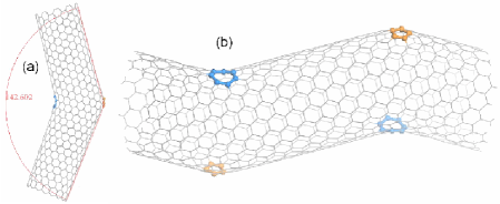
Now, we firstly calculate the vibrational spectrum of a SWNT IMJ constructed by the (10, 10) and (17, 0) tubes with almost the same radii, whose structures are shown in Fig. 2. In order to eliminate the effect of dangling bonds, we further connect two same (10, 10)-(17, 0) SWNT IMJs to build a periodic structure shown in the right panel of Fig. 2, which is studied in this work. Then a structural optimization is performed to prevent the appearance of imaginary frequency, i.e., the soft mode.
In Fig. 3, the nonresonant Raman spectra of some structures are presented. Because the low frequency band and the high frequency band are mostly interested in experiment, only those two frequency ranges, i.e., 0-400 cm-1 and 1400-2100 cm-1, are shown in Fig. 3.
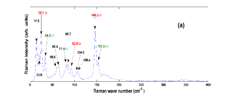


Comparing Fig. 3a and 3c, it is clearly seen that many small peaks appear in the low frequency part. Some of them come from the original SWNT components, and their frequency numbers are affixed by letters of ( or (, indicating, respectively, the corresponding vibration mode comes from the in-phase or counter-phase combination of the Raman modes in two SWNTs. For example, the peak at 25.2 cm-1 roots in the in-phase combination of the modes of (10, 10) and (17, 0) tubes, but the peak at 34.3 cm-1 comes from their counter-phase combination. Their atomic vibrations have been shown in Fig. 4, from which it is clearly seen that the atomic motions on the (10, 10) and (17, 0) tubes are in the same direction for 25.2 cm-1 mode, whereas they are in the reverse directions for 34.3 cm-1 mode.

Some other peaks in the low frequency part, e.g., the peaks at 14.5, 20.6, 60.0, 65.5, 85.7 and 108.4 cm-1, can not find their counterparts in the Raman spectra of the original SWNTs. Some of them come from the symmetry breaking of the perfect nanotube, and some others come from the vibration of the connecting part of the IMJ. For example, the atomic vibrations of 65.5, 85.7 and 108.4 cm-1 modes are shown in Fig. 5. Obviously, the atomic motions near the defect parts are larger than those on the tube. But, most probably, it is practically difficult to observe these peaks because the most intensive low frequency peak found in experiments is the band caused by RBM mode.

As for the high frequency part, it can be found from Fig. 3b and 3d that many peaks appear in the band (1600-1800 cm. A superposition of these peaks forms a widely distributed band, which could not be regarded as a simple superposition of those bands from the original SWNTs. This phenomenon has been observed in the experimental result of Ref. r21, , making also the detailed analysis on the band of SWNT IMJ very complicated and hardly to be performed.
On the other hand, in the range out of band, i.e., in a range of about 1800-2050 cm-1, some other Raman peaks can be found, whose modes are much simpler than the band, and so may offer some useful information about the topological structures of SWNT IMJs.

In order to understand the origin of these modes, their atomic vibrations are presented in Fig. 6. Obviously, these modes have a common character that their vibrational amplitudes are the largest on the pentagon ring, and become smaller and smaller on the other atoms of the tube surface when the atoms lie from the pentagon ring farther and farther. In other words, these modes are defect states caused by the pentagon ring. So, the pentagon can be regarded as a “topological impurity” in the perfect SWNT. Here, it is found that the bond length on the hexagon rings is about 1.42 Å, while the mean bond lengths on the pentagon and heptagon rings are about 1.37 and 1.45 Å, respectively. This fact means that the force constants on the pentagon (heptagon) defects should be larger (smaller) relative to those on the hexagon rings. Also, the distance between the pentagon and heptagon defects is quite large so that their interaction can be neglected. So, we can simply use the one dimensional (1D) single impurity model in the classical solid state theory r36 to discuss qualitatively the vibrational property of here’s (10, 10)-(17, 0) SWNT IMJ, and find that the frequency of the “topological impurity” state could be written as
| (2) |
Here, and are the force constant of the “topological impurity” and the 1D perfect lattice, respectively, with its maximum vibrational frequency of . And is the atom mass. Eq. 2 is valid when , which evidently corresponds to the situation of the pentagon defects. From Eq. 2, one can find that the defect frequency is higher than the maximum frequency of the perfect lattice, which is also well consistent with our numerical result. Furthermore, if we use the technical term in the traditional mass-impurity model in the classical solid state theory r36 , one may consider the pentagon defect to be the “light-mass impurity”. But the frequency of the localized defect state can not be simply obtained from Eq. 2 because it is difficult to make a direct link between the simple model and the realistic structure.
Since the pentagon defect can cause localized defect state, then how about the heptagon defect? After searching for the whole Raman spectrum, we find that it is very hard to induce the localized states on the heptagon defect. The atomic vibrations of its two strongest defect states are shown in Fig. 7, which is found to be much weaker than those in pentagon defect states. Correspondingly, the Raman intensities of these modes are much weaker too. This phenomenon can be understood as follows. Similar to the case of pentagon defect, the heptagon defect can be regarded as the “heavy impurity” in the traditional mass-impurity model, which mainly causes the phase shift of the vibrational modes. And the frequencies of the localized modes caused by the “heavy impurity” are all lower than the maximum vibrational frequency of the perfect lattice, which is also consistent with our numerical result.

To further validate our finding about the localized states, the first-principles calculation is made to study the vibrational properties of the pentagon-heptagon defects. But as indicated, the first-principles calculation on the SWNT IMJs is too expensive, and so is made on another substitute structure, i.e., a graphene sheet with a Stone-Wales (SW) defect on it. The SW defect is two pairs of pentagon-heptagon defects got together, and can be generated by rotating one bond in the graphene sheet by 90o. Now, the K-points sampling in the reciprocal space is a uniform grid in the graphene sheet and the maximum spacing between k points is still 0.03 Å-1.
Firstly, the nonzero vibrational modes in a perfect graphene are calculated by the first-principles method, which is found to be 1591.38, 1591.14, and 896.24 cm-1, and similar to the results in Ref. r27, . Then, we have performed the calculation on a periodical (66) graphene unit cell with a SW defect in its center. The distance between nearby graphene sheets is fixed to be 15 Å, which is large enough to neglect the interaction between the sheets. Structural optimization is also made to prevent the soft modes. In such a structure, the distance between the SW defects is 14.5 Å, which is also large enough to neglect the interaction between neighbor SW defects.


The obtained results for three kinds of localized states are shown in Fig. 8, 9 and 10. The localized states caused by pentagon defects are presented in Fig. 8, from which one can find their frequencies are very large, and those modes with larger frequencies tend to be more localized on the pentagon rings. For the localized states caused by heptagon defects shown in Fig. 9, the modes with larger frequencies also tend to be more localized on the heptagon rings, but their largest frequency is about 1356 cm-1, which is still lower than the band frequency of graphene. All these phenomena agree qualitatively with our REBO results and the discussions based on the simple model.
The localized modes in Fig. 10 can not be simply considered to be localized on which defects. In fact, they distribute on the whole SW defect, which means they are caused by the whole SW defect. On the other hand, their appearance also indicates that the distance between pentagon and heptagon rings has a great inference on the behavior of localized states.
Quantitatively, the highest frequency of the localized states on the pentagon rings in the SWNT IMJs should be higher than 1820 cm-1 due to the curvature effect of nanotubes. In fact, in Ref. r37, , the authors studied the vibrational property of the small diameter (3, 3) SWNT with SW defect and found a local defect vibration mode with its frequency of 1962 cm-1 due to large curvature effect of the (3, 3) SWNT, which could be served as a fingerprint of the SW defect in carbon nanotubes. From our foregoing discussion, it can be deduced that this local defect vibration mode is just the highest frequency localized mode mainly caused by the pentagon defects.
Now, we want to study the relationship of the localized mode frequency with the defect positions, and so make calculations on two structures, i.e., two (5, 5)-(10, 10) SWNT IMJs connected by different methods, whose structures are shown in Fig. 11.

The symmetry group of the first SWNT IMJ (Fig. 11a-11c) is , which is called as the HS (high symmetry) SWNT IMJ. The symmetry group of the second SWNT IMJ (Fig. 11d-11f) is , which is called as the LS (low symmetry) SWNT IMJ. Beside their different symmetries, there are also another two important differences between them, which are the junction length defined as the distance between the pentagon-heptagon defects, and the number of pentagon-heptagon defects. There are five pairs of pentagon-heptagon defects in the HS SWNT IMJ, and only one pair of pentagon-heptagon defects in the LS SWNT IMJ.
Now we will pay our attention only to the high frequency part of the Raman spectra of these two SWNT IMJs, which have been shown in Fig. 12. It can be found from Fig. 12 that the band of the LS SWNT IMJ extends into a wider region than that of the HS SWNT IMJ. This should root in the long transition region in the LS SWNT IMJ, in which the IMJ radius and the bond lengths change almost continuously. So, most probably, the SWNT IMJ with a longer junction region will have a wider band, which could be observed experimentally.


In addition, one can find that the intensities of the highest frequency localized modes in the two SWNT IMJs are very different. In other words, relative to the band intensity, the highest frequency localized mode in the HS SWNT IMJ has a larger intensity than that in the LS SWNT IMJ, which is probably due to the fact that there exist five times more pentagon-heptagon defects in the HS SWNT IMJ than in the LS SWNT IMJ. So the intensity of the highest frequency localized mode could be used to determine the number of pentagon rings experimentally. Once the number of pentagon rings is determined, the number of heptagon rings can be determined too by Eq. 1. Generally speaking, nice reference samples with a ‘known’ number of pentagons will be greatly helpful to determine the accurate number of defects in the IMJ, which is probably a technically difficult at the present time. However, with improving gradually the experimental tools, the nice sample could be manufactured in future. In a word, we think it is possible to use this method to determine the number of pentagon defects after we can set up a standard for it by measuring the nice reference sample with a ”known” number of pentagons, e.g., a perfect SWNT with a cap at its end, which has six pentagons, or the SWNT with a Stone-Wales defect, which is composed of two pentagon-heptagon pairs next to each other. At least, probably this method could give an approximate number of pentagons in the SWNT IMJ. Finally, we also hope that it can be combined with other experimental methods, e.g., the optical responses to reach more practically this goal.
IV Conclusions
In this work, the vibrational modes of some SWNT intramolecular junctions have been calculated by using the newest Tersoff-Brenner potential. Furthermore, using the empirical bond polarizability model, the nonresonant Raman spectra of these SWNT IMJs have been calculated. It is found that the highest frequency localized states caused by pentagon defects could be used to identify accurately detailed geometrical structure of the SWNT IMJ. That is because its frequency lies out of the band of SWNTs and can be distinguished easily. And its intensity has a close relation with the number of pentagon defects. On the other hand, it is found that the heptagon defects can only cause weak localized states below the band of SWNTs and can hardly be observed in experiments. All these results could be qualitatively explained by a simple “topological impurity” model. The first-principles calculations are also carried out to further prove our results quantitatively, and show that the characteristic frequency of the SW defects should lie between 1820 and 1962 cm-1, depending on the local curvature of the tube. Furthermore, the junction length is shown to have an important effect on the band width of the SWNT IMJ, i.e., the shorter transition region will make the band of SWNT IMJ to be narrower and simpler. Finally, the intensity of the Raman spectra has a close relation with the number of topological defects.
Acknowledgements.
The authors acknowledge support from the Natural Science Foundation of China under Grant No. 10474035 and No. 90503012, and also support from a Grant for State Key Program of China through Grant No. 2004CB619004.References
- (1) M.S. Dresselhaus, G. Dresselhaus, and Ph. Avouris, Carbon Nanotubes: Synthesis, Structure, Properties and Applications, Vol. 80 of Springer Series in Topics in Applied Physics (Springer-Verlag, Berlin, 2001).
- (2) P. Avouris, Acc. Chem. Res. 35, 1026 (2002).
- (3) A. Bachtold, P. Hadley, T. Nakanishi, and C. Dekker, Physica (Amsterdam) 16E, 42 (2003).
- (4) J.A. Misewich, R. Martel, P. Avouris, J.C. Tsang, S. Heinze, and J. Tersoff, Science 300, 783 (2003).
- (5) B. I. Dunlap, Phys. Rev. B 49, 5643 (1994).
- (6) J.-C. Charlier, T.W. Ebbesen, and Ph. Lambin, Phys. Rev. B 53, 11 108 (1996).
- (7) L. Chico, V. H. Crespi, L. X. Benedict, S. G. Louie, and M. L. Cohen, Phys. Rev. Lett. 76, 971 (1996).
- (8) R. Saito, G. Dresselhaus, and M. S. Dresselhaus, Phys. Rev. B 53, 2044 (1996).
- (9) V. Meunier, P. Senet, and Ph. Lambin, Phys. Rev. B 60, 7792 (1999).
- (10) M. S. Ferreira, T. G. Dargam, R. B. Muniz, and A. Latgé, Phys. Rev. B 62, 16040 (2000).
- (11) W. Fa, J.W. Chen, H. Liu, and J.M. Dong, Phys. Rev. B 69 (23), 235413 (2004).
- (12) L.F. Yang, J.W. Chen, H.T. Yang, and J.M. Dong, Euro. Phys. J. B 33 (1), 215 (2003).
- (13) Jie Han, M. P. Anantram, R. L. Jaffe, J. Kong and H. Dai, Phys. Rev. B 57, 14983 (1998).
- (14) W. Fa, X. Yang, J. Chen, and J. Dong, Phys. Lett. A 323, 122 (2004).
- (15) Y. Zhen, W. Ch. P. Henk, B. Leon, and D. Cees, Nature (London) 402, 273 (1999).
- (16) H.W.Ch. Postma, M. de Jonge, Z. Yao, and C. Dekker, Phys. Rev. B 62, R10653 (2000)
- (17) M.S. Fuhrer, A.K.L. Lim, L. Shih, U. Varadarajan, A. Zettl, and P.L. McEuen, Physica E 6, 868 (2000).
- (18) J.W. Park, J. Kim, and K.H. Yoo, J. App. Phys. 93, 4191 (2003).
- (19) M. Ouyang M, J.L. Huang, C.L. Cheung, and C.M. Lieber, Science 291, 97 (2001).
- (20) H. Kim, J. Lee, S.-J. Kahng, Y.-W. Son, S. B. Lee, C.-K. Lee, J. Ihm, and Young Kuk, Phys. Rev. Lett. 90, 216107 (2003).
- (21) L. Vitali, M. Burghard, M. A. Schneider, L. Liu, S.Y. Wu, C. S. Jayanthi, and K. Kern, Phys. Rev. Lett. 93, 136103 (2004).
- (22) S. K. Doorn, M. J. O’Connell, L. Zheng, Y. T. Zhu, S, Huang, and J. Liu, Phys. Rev. Lett. 94, 016802 (2004).
- (23) R. Saito, T. Takeya, T. Kimura, G. Dresselhaus, and M. S. Dresselhaus, Phys. Rev. B 57, 4145 (1998).
- (24) P. Pavone, K. Karch, O. Schütt, W. Windl, D. Strauch, P. Giannozzi, and S. Baroni, Phys. Rev. B 48, 3156 (1993).
- (25) G. Kresse, J. Furthmüller, and J. Hafner, Europhys. Lett. 32, 729 (1995).
- (26) O. Dubay and G. Kresse, Phys. Rev. B 67, 035401 (2003).
- (27) L.H. Ye, B.G. Liu, D.S. Wang, and R. Han, Phys. Rev. B 69, 235409 (2004).
- (28) G. Wu, J. Zhou, and J. Dong, Phys. Rev. B 72, 115411 (2005).
- (29) D.W. Brenner, O.A. Shenderova, J. A. Harrison, S. J. Stuart, B. Ni, and S. B. Sinnott, J. Phys.: Condens. Matter 14, 783 (2002).
- (30) D.W. Brenner, Phys. Rev. B 42, 9458 (1990).
- (31) R. Saito, T. Takeya, T. Kimura, G. Dresselhaus, and M.S. Dresselhaus, Phys. Rev. B 57, 4145 (1998); S. Guha, J. Menendez, J.B. Page, and G.B. Adams, Phys. Rev. B 53, 13106 (1996).
- (32) D. Kahn, and J. P. Lu, Phys. Rev. B 60, 6535 (1999).
- (33) P.E. Blöchl, Phys. Rev. B 50, 17 953 (1994); G. Kresse and D. Joubert, ibid. 59, 1758 (1999).
- (34) G. Kresse and J. Hafner, Phys. Rev. B 47, R558 (1993); 49, 14251 (1994); G. Kresse and J. Furthmüller, Comput. Mater. Sci. 6, 15 (1996).
- (35) R. Saito, G. Dresselhaus, and M.S. Dresselhaus, Physical Properties of Carbon Nanotubes (London: Imperial College Press, 1998).
- (36) Z. Li, Solid State Theory, second ed., in Chinese (Beijing: High Education Press, 2002), Section 10.6; O. Madelung, Introduction to Solid State Theory (New York: Springer Press, 1980) Chap 9.
- (37) Y. Miyamoto, A. Rubio, S. Berber, M. Yoon, and D. Tománek, Phys. Rev. B 69, 121413(R) (2004).