Singular point characterization in microscopic flows
Abstract
We suggest an approach to microrheology based on optical traps in order to measure fluid fluxes around singular points of fluid flows. We experimentally demonstrate this technique, applying it to the characterization of controlled flows produced by a set of birefringent spheres spinning due to the transfer of light angular momentum. Unlike the previous techniques, this method is able to distinguish between a singular point in a complex flow and the absence of flow at all; furthermore it permits us to characterize the stability of the singular point.
pacs:
47.61.-k, 47.60.+i, 87.80.Cc, 05.40.JcThe experimental characterization of fluid flows in
micro-environments is important both from a fundamental point of
view and from an applied one, since for many applications it is
required to assess the performance of microfluidic structures,
such as lab-on-a-chip devices Knight (2002). Carrying out this
kind of measurements can be extremely challenging. In particular,
due to the small size of these environments, wall effects can not
be neglected Zhu and Granick (2001). Additional difficulties arise
studying biological fluids because of their complex rheological
properties.
In the cases of practical interest the flow is strongly viscous
(creeping motions or Stokes flows) and a low Reynolds number
regime can be assumed Happel and Brenner (1983). Since the creeping motion regime is a particular
case of a laminar regime, it is possible to univocally define a
time-independent pressure and velocity field. Therefore,
for each position a well-defined drag force acts on a particle immersed in the fluid flow.
Ideally micro-flow sensors should be able to monitor the
streamlines in real time and in the least invasive way. One common
method to achieve this goal is to measure the drag force field
acting on a probe particle, resorting to statistical criteria of
analysis because of the intrinsic presence of Brownian motion.
Recently optically trapped microscopic particles have been
proposed as flow sensors
Nemet and Cronin-Golomb (2002); Bishop et al. (2004); Knöner et al. (2005); Pesce et al. (2006); Di Leonardo et al. (2006).
An optical trap enables the confinement of micron sized objects: a
high numerical aperture objective lens is used to tightly focus an
optical beam and to produce a force sufficient to hold dielectric
objects ranging in size from 100 s of nanometers to 10 s of
microns Neuman and Block (2004). In Nemet and Cronin-Golomb (2002) an oscillating
optically trapped probe is used to map the two-dimensional flow
past a microscopic wedge. In Bishop et al. (2004) and
Knöner et al. (2005) a stress microviscometer is presented: it
generates and measures microscopic fluid velocity fields,
monitoring the probe particle displacement, which is directly
converted into velocity field values, through digital video
microscopy. A further improvement was achieved in
Di Leonardo et al. (2006) by using multiple holographic optical traps
in order to parallelize the technique: an array of micro-probes
can be simultaneously trapped and used to map out the streamlines
in a microfluidic device. All these techniques apply a Photonic
Force Microscope (PFM) approach
Ghislain and Webb (1993); E. Florin and Stelzer (1997); Rohrbach and Stelzer (2002); Berg-Sørensen and
Flyvbjerg (2004) to
the flow measurement: the fluid velocity at the trap location is
obtained by monitoring the probe displacements resulting from the
balance between the trapping and drag forces.
All the techniques described above present a major drawback: they
interpret the experimental results assuming that the flow can be
described by a set of parallel streamlines. When this is the case,
the drag force acting on a probe around a specific point in the
flow is well described by a constant value, and this is the case
considered by the current optical trap methods. However, in the
drag force-field there may be singular points as well. In these
points the flow and, hence, the drag force are null, but not in
its surrounding. The question, which arises naturally, is how to
characterize this case. Under the assumption of a steady
incompressible flow, a zero body force and low Reynolds numbers,
the local fluid motion satisfies the quasi-static Stokes equations
Happel and Brenner (1983): ,
, where is the velocity,
is the pressure and the dynamic viscosity. Since the
fluid is incompressible and there are no sources or sinks, there
can be only two kinds of singular points M.W.Hirsch and Devaney (San Diego, 2004): (1)
saddles (unstable) at the meeting point between two opposite
flowing streamlines or (2) centra (stable) in presence of a
non-zero curl. As we show below, the characterization of the flow
near these points can be achieved by studying the statistical
properties of the Brownian motion of the probe.
The knowledge of the flow-field near a singular point is of
relevance for fundamental physical studies as well as for
engineering applications. The mixing of fluids flowing through
microchannels is important for many chemical application; a
reduction of the mixing length can be achieved by the generation
of a transverse flow Stroock et al. (2002), case in which the
formation of singular points is inevitable. In biological systems
creeping motions take place in small blood or linfatic vessel or
at the interface between tissues and prothesis or artificial
organs Belanger (1990). In the presence of slow flows, macrophage
adhesion becomes more probable, increasing the possibilities of
inflammation. Furthermore, the growth rate of thrombi, due to
platelet aggregation, is also determined by the characteristics of
the flow around it: for example, the presence of stable
equilibrium points, such as centra, helps their formation and
growth Liu et al. (2002). Flow measurements at the microscale can
help to diagnose pathologies and to guide the design of
bio-materials and nano-devices for diagnostic or therapeutic
goals.
In this letter we extend the PFM-approach to microrheology in order to measure and characterize fluid fluxes in the proximity of singular points. The concept is to monitor the position of an optically trapped probe in order to locally characterize the drag force field as a generic function of the space coordinates up to the first order in its Taylor expansion around the probe position Volpe et al. (2007). This technique permits us to distinguish between a singular point in a complex flow and the absence of flow at all. Furthermore our approach allows one to determine the stability of these singular points, which can be relevant for applications.
In the following we will consider the drag force field produced by a bidimensional laminar regime. Since in microfluidic and lab-on-a-chip devices a planar geometry is generally assumed, this is the most useful case for applications. Nevertheless, if needed, our approach can be generalized to the three-dimensional case.
Experimentally, we generated these three kinds of fluid flow - namely a set of parallel streamlines, a saddle or a centrum - using solid spheres made of a birefringent material (Calcium Vaterite Crystals (CVC) spheres, radius Bishop et al. (2004)), which can be made spin due to the transfer of orbital angular momentum of light. They are all-optically controlled, i.e. their position can be controlled by an optical trap and their spinning state can be controlled through the polarization state of the light. The angular velocity of the CVC sphere is given by , where is the change of the light spin momentum due to the scattering on the probe, is the beam power, is the medium viscosity, is the speed of light, and is the wavelength of the optical field. In the experimental realization up to four CVC spheres were optically trapped in water and put into rotation using four steerable beams from a Nd:YAG laser with controllable polarization - to control the direction of the rotation - and power - to control the rotation rate. A probe polystyrene sphere (radius ) was held by an optical trap produced by a linearly polarized beam. The stiffness of this trap was adjustable through the power. The forward scattered light of this latter beam served to track the probe position using a position sensor based on a quadrant-photodetector (QPD).
Assuming no slip at the particle surface, the quasi-Stokes equation leads to the following solution for the flow velocity near a single spinning sphere Happel and Brenner (1983); Knöner et al. (2005)
| (1) |
In each point near the rotating sphere
the streamlines are perpendicular to the plane containing the -axis
(unit vector ) and the coordinate vector
.
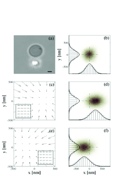
In Fig. 1 the results for probing such a drag force field near a single spinning sphere are presented. The CVC sphere is put into rotation at . The induced drag force can be measured through the shift of the equilibrium position of the probe (Fig. 1(b), 1(d), and 1(f)) and after calibrating the stiffness of the probe trap (). The corresponding force field can be reconstructed (Fig. 1(c) and 1(e)): the forces acting on the probe particle result (counterclockwise rotation) and (clockwise rotation). These results are in agreement with Bishop et al. (2004); Knöner et al. (2005).
In a system with spinning spheres, the linearity of the quasi-Stokes equations Happel and Brenner (1983) allows one to use the superposition of solutions (1) in order to obtain the total flow. Since the velocity in the equatorial plane is proportional to the reciprocal square of the distance from the sphere center, the flow velocity vanishes at a distance of a few sphere radii. Hence, in first approximation the hydrodynamic interaction between the spinning spheres located far enough from each other can be neglected. For or we assume the spheres to be symmetrically displaced at the same distance with respect to the origin (Fig. 3(a) and 4(a)), so that the origin is a singular point, i.e. . The velocity field can be locally approximated as
| (2) |
where is the Jacobian matrix of the total velocity
field evaluated in the singular point and the
Jacobian matrix of the velocity field generated by particle
evaluated in the same point. As expected, since the fluid is
incompressible, is always null. This means that
only (unstable) saddles - with , - or (stable) centra - with , - can exist.
In Fig. 2 to 4 the experimental results for such cases are
presented. We followed the data analysis procedure proposed in
Volpe et al. (2007), to which we refer for the full details. The
total force field acting on the probe is given by the sum of the
drag force-field and the restoring force due to the harmonic
trapping potential. The drag force field can be decomposed into a
conservative and a rotational part, while the optical force field
is purely conservative. The cross-correlation function (CCF)
between the and position of the probe, calculated as
,
does not vanish only if the rotational part of the drag force
field is not null. The rotational component of the drag force
field can be obtained from the CCF
Volpe and Petrov (2006); Volpe et al. (2007). If the rotational component,
and therefore the CCF, is null, the total force field is purely
conservative, and the conservative component of the drag force
field can be calculated by subtracting the optical potential from
the total potential. We underline that this can only be done if
the total force field is conservative. Some results for an
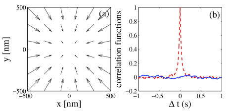
optically trapped probe in the absence of flow are presented in
Fig. 2: the optical force-field is harmonic (Fig. 2(a)) and it is
purely conservative, as it is shown by the fact that its CCF
function is null (Fig. 2(b)).
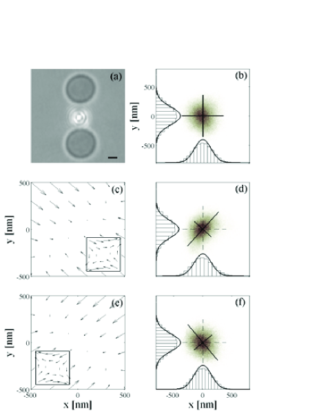
In Fig. 3 the flow to be probed is generated putting into rotation
() two CVCs, symmetrically positioned
with respect to the probe beads (Fig. 3(a)). The position of the
probe is chosen so that there is no shift in the equilibrium
position regardless of the rotation state of the spheres (Fig.
3(b), 3(d), and 3(f)). Since the experimental CCF is found to be
null within the experimental error, we conclude that the
rotational component of the drag force field must be negligible
and we can reconstruct its conservative part by subtracting the
optical restoring force-field from the total force field (Fig.
3(c) and 3(e)). The optical trap produces a symmetric harmonic
potential () (Fig. 3(b)). With spinning CVCs
the PDF becomes ellipsoidal (Fig. 3(d) and 3(f)). For a clockwise
rotation (Fig. 3(c-d)), the main axes of the ellipses are oriented
at , the stiffness is along
the main axis and along the secondary
axis. For a counterclockwise rotation (Fig. 3(e-f)), the main axes
of the ellipses are oriented at , the stiffness is
along the main axis and along the secondary axis. The difference are
due to the fact that the rotation rate was observed to be
different in the two directions. The corresponding total force
fields are represented in Fig. 3(c) and 3(e), while the drag force
field contributions are depicted in the insets: they constitute
indeed saddle points.
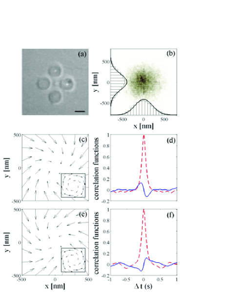
In Fig. 4 the characterization of a fluid flow near a singular point of the second kind, a centrum, is presented. This stable singular point was generated putting into rotation () four birefringent spheres symmetrically distributed with respect to the probe (Fig. 4(a)) in an optical trap with stiffness . We can observe that the PDF of the probe position do not depend on the rotation direction of the spinning spheres (Fig. 4(b)); however, in this case the CCF is not null (Fig. 4(d) and 4(f)), showing the presence of a rotational component of the drag force field. This component is such that it produces a torque on the probe bead, whose angular velocity is , as for the beads rotating clockwise (Fig. 4(c-d)) and for the case of the beads rotating counterclockwise (Fig. 4(e-f)). The resulting total and drag force fields are represented in Fig 4(c) and 4(e), while the drag force field contributions are depicted in the insets: they constitute, indeed, a centrum.
In conclusion, we have demonstrated the use of an optically trapped probe for the characterization of singular points in microscopic flows. This technique delivers an important contribution towards a better understanding and optimization of microfluidic flows in the presence of singular points, providing both a deeper understanding of their physics and an experimental approach to their characterization. Furthermore our approach allows one to determine the stability of these singular points, which can be relevant for applications.
Acknowledgements.
The authors acknowledge useful discussions with N. Heckenberg, A. Bagno, and M. Rubí. This research was carried out in the framework of ESF/PESC (Eurocores on Sons), through grant 02-PE-SONS-063-NOMSAN, and with the financial support of the Spanish Ministry of Education and Science. It was also partially supported by the Departament d’Universitats, Recerca i Societat de la Informació and the European Social Fund.References
- Knight (2002) J. Knight, Nature 418, 474 (2002).
- Zhu and Granick (2001) Y. Zhu and S. Granick, Phys. Rev. Lett. 87, 096105 (2001).
- Happel and Brenner (1983) J. Happel and H. Brenner, Low Reynolds Number Hydrodynamics (Spinger, New York, 1983).
- Nemet and Cronin-Golomb (2002) B. A. Nemet and M. Cronin-Golomb, Opt. Lett. 27, 1357 (2002).
- Bishop et al. (2004) A. I. Bishop, T. A. Nieminen, N. R. Heckenberg, and H. Rubinsztein-Dunlop, Phys. Rev. Lett. 92, 198104 (2004).
- Knöner et al. (2005) G. Knöner, S. Parkin, N. R. Heckenberg, and H. Rubinsztein-Dunlop, Phys. Rev. E 72, 031507 (2005).
- Pesce et al. (2006) G. Pesce, A. Sasso, and S. Fusco, Rev. Sci. Instrumen. 76, 115105 (2006).
- Di Leonardo et al. (2006) R. Di Leonardo, J. Leach, H. Mushfique, J. M. Cooper, G. Ruocco, and M. J. Padgett, Phys. Rev. Lett. 96, 134502 (2006).
- Neuman and Block (2004) K. C. Neuman and S. M. Block, Rev. Sci. Instrumen. 75, 2787 (2004).
- Ghislain and Webb (1993) L. Ghislain and W. W. Webb, Opt. Lett. 18, 1678 (1993).
- E. Florin and Stelzer (1997) J. H. E. Florin, A. Pralle and E. Stelzer, J. Struct. Bio. 119, 202 (1997).
- Rohrbach and Stelzer (2002) A. Rohrbach and E. Stelzer, J. App. Phys. 91 (2002).
- Berg-Sørensen and Flyvbjerg (2004) K. Berg-Sørensen and H. Flyvbjerg, Rev. Sci. Instrumen. 75, 594 (2004).
- M.W.Hirsch and Devaney (San Diego, 2004) S. S. M.W.Hirsch and R. Devaney, Differential Equations, Dynamical Systems, and an Introduction to Chaos (San Diego, 2004).
- Stroock et al. (2002) A. D. Stroock, S. K. W. Dertinger, A. Ajdari, I. Mezić, H. A. Stone, and G. W. Whitesides, Science 295 (2002).
- Belanger (1990) A. Belanger, Vascular Anatomy and Physiology: An Introductory Text (Davies publishing, Inc., 1990).
- Liu et al. (2002) S. Q. Liu, L. Zhong, and J. Goldman, Trans. ASME 124, 30 (2002).
- Volpe et al. (2007) G. Volpe, G. Volpe, and D. Petrov (2007).
- Volpe and Petrov (2006) G. Volpe and D. Petrov, Phys. Rev. Lett. 97, 210603 (2006).