Coherent Control of a Single Electron Spin with Electric Fields
Manipulation of single spins is essential for spin-based quantum information processing. Electrical control instead of magnetic control is particularly appealing for this purpose, since electric fields are easy to generate locally on-chip. We experimentally realize coherent control of a single electron spin in a quantum dot using an oscillating electric field generated by a local gate. The electric field induces coherent transitions (Rabi oscillations) between spin-up and spin-down with rotations as fast as 55 ns. Our analysis indicates that the electrically-induced spin transitions are mediated by the spin-orbit interaction. Taken together with the recently demonstrated coherent exchange of two neighboring spins, our results demonstrate the feasibility of fully electrical manipulation of spin qubits.
Spintronics and spin-based quantum information processing provide the possibility to add new functionality to today’s electronic devices by using the electron spin in addition to the electric charge [1]. In this context, a key element is the ability to induce transitions between the spin-up and spin-down states of a localized electron spin, and to prepare arbitrary superpositions of these two basis states. This is commonly accomplished by magnetic resonance, whereby bursts of a resonant oscillating magnetic field are applied [2]. However, producing strong oscillating magnetic fields in a semiconductor device requires specially designed microwave cavities [3] or microfabricated striplines [1], and has proven to be challenging. In comparison, electric fields can be generated much more easily, simply by exciting a local gate electrode. In addition, this allows for greater spatial selectivity, which is important for local addressing of individual spins. It would thus be highly desirable to control the spin by means of electric fields.
Although electric fields do not couple directly to the electron spin, indirect coupling can still be realized by placing the spin in a magnetic field gradient [5] or in a structure with a spatially varying -tensor, or simply through spin-orbit interaction, present in most semiconductor structures [6, 7]. Several of these mechanisms have been employed to electrically manipulate electron spins in two dimensional electron systems [8, 9, 10, 11], but proposals for coherent electrical control at the level of a single spin [12, 13, 5, 14, 15] have so far remained unrealized.
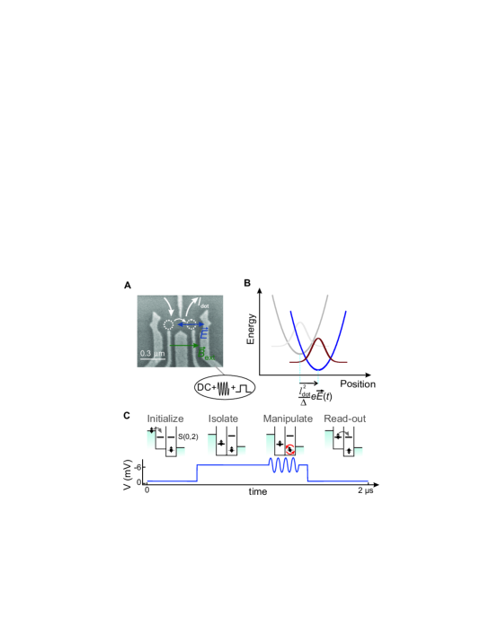
We demonstrate coherent single spin rotations induced by an oscillating electric field. The electron is confined in a gate-defined quantum dot (see Fig. 1A) and we use an adjacent quantum dot, containing one electron as well, for read-out. The ac electric field is generated through excitation of one of the gates that forms the dot, thereby periodically displacing the electron wavefunction around its equilibrium position (Fig. 1B).
The experiment consists of four stages (Fig. 1C). The device is initialised in a spin-blockade regime where two excess electrons, one in each dot, are held fixed with parallel spins (spin triplet), either pointing along or opposed to the external magnetic field (the system is never blocked in the triplet state with anti-parallel spins, because of the effect of the nuclear fields in the two dots combined with the small interdot tunnel coupling, see [16] for full details). Next, the two spins are isolated by a gate voltage pulse, such that electron tunneling between the dots or to the reservoirs is forbidden. Then, one of the spins is rotated by an ac voltage burst applied to the gate, over an angle that depends on the length of the burst [17] (most likely the spin in the right dot, where the electric field is expected to be strongest). Finally, the read-out stage allows the left electron to tunnel to the right dot if and only if the spins are anti-parallel. Subsequent tunneling of one electron to the right reservoir gives a contribution to the current. This cycle is continuously repeated, and the current flow through the device is thus proportional to the probability of having antiparallel spins after excitation.
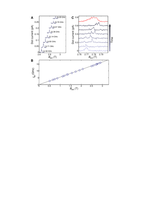
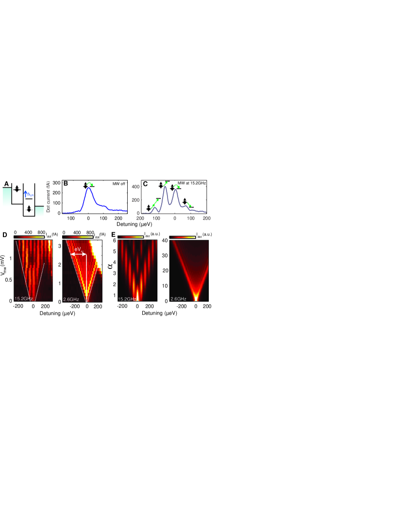
To demonstrate that electrical excitation can indeed induce single-electron spin flips, we apply a microwave burst of constant length to the right side gate and monitor the average current flow through the quantum dots as a function of external magnetic field (Fig. 2A). A finite current flow is observed around the single-electron spin resonance condition, i.e. when , with Planck’s constant, the excitation frequency, and the Bohr magneton. From the position of the resonant peaks measured over a wide magnetic field range (Fig. 2B) we determine a -factor of , which is in agreement with other reported values for electrons in GaAs quantum dots [18].
In addition to the external magnetic field, the electron spin feels an effective nuclear field arising from the hyperfine interaction with nuclear spins in the host material and fluctuating in time [19, 20]. This nuclear field modifies the electron spin resonance condition and is generally different in the left and right dot (by ). The peaks shown in Fig. 2A are averaged over many magnetic field sweeps and have a width of about 10-25 mT. This is much larger than the expected linewidth, which is only 1-2 mT given by the statistical fluctuations of [21, 4]. Looking at individual field sweeps measured at constant excitation frequency, we see that the peaks are indeed a few mT wide (see Fig. 2C), but that the peak positions change in time over a range of 20mT. Judging from the dependence of the position and shape of the averaged peaks on sweep direction, the origin of this large variation in the nuclear field is most likely dynamic nuclear polarization [23, 24, 1, 25, 26].
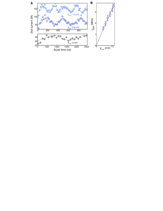
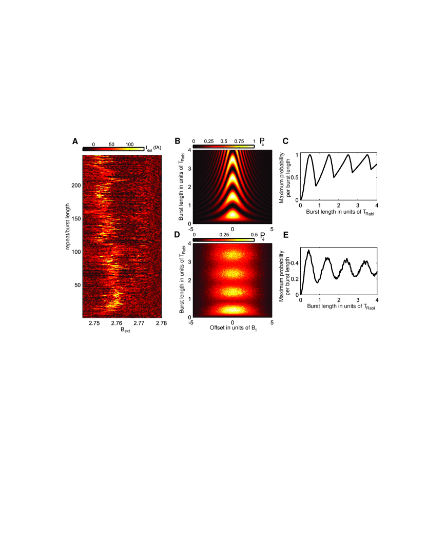
In order to demonstrate coherent control of the spin, the length of the microwave bursts was varied, and the current level monitored. In Fig. 3A we plot the maximum current per magnetic field sweep as a function of the microwave burst duration, averaged over several sweeps (note that this is a more sensitive method than averaging the traces first and then taking the maximum)[17]. The maximum current exhibits clear oscillations as a function of burst length. Fitting with a cosine function reveals a linear scaling of the oscillation frequency with the driving amplitude (Fig. 3B), a characteristic feature of Rabi oscillations, and proof of coherent control of the electron spin via electric fields.
The highest Rabi frequency we achieved is MHz (measured at GHz) corresponding to a rotation in ns, which is only a factor of two slower than those realized with magnetic driving [1]. Stronger electrical driving was not possible because of photon-assisted-tunneling. This is a process whereby the electric field provides energy for one of the following transitions: tunneling of an electron to a reservoir or to the triplet with both electrons in the right dot. This lifts spin-blockade, irrespective of whether the spin resonance condition is met.
Small Rabi frequencies could be observed as well. The bottom trace of Fig. 3A shows a Rabi oscillation with a period exceeding s (measured at GHz), corresponding to an effective driving field of only about 0.2 mT, ten times smaller than the statistical fluctuations of the nuclear field. The reason the oscillations are nevertheless visible is that the dynamics of the nuclear bath is slow compared to the Rabi period, resulting in a slow power law decay of the oscillation amplitude on driving field [3].
We next turn to the mechanism responsible for resonant transitions between spin states. First, we exclude a magnetic origin as the oscillating magnetic field generated upon excitation of the gate is more than two orders of magnitude too small to produce the observed Rabi oscillations with periods up to ns, which requires a driving field of about 2mT [17]. Second, we have seen that there is in principle a number of ways in which an ac electric field can cause single spin transitions. What is required is that the oscillating electric field give rise to an effective magnetic field, , acting on the spin, oscillating in the plane perpendicular to , at frequency . The -tensor anisotropy is very small in GaAs so g-tensor modulation can be ruled out as the driving mechanism. Furthermore, in our experiment there is no external magnetic field gradient applied, which could otherwise lead to spin resonance [5]. We are aware of only two remaining possible coupling mechanisms: spin-orbit interaction and the spatial variation of the nuclear field.
In principle, moving the wavefunction in a nuclear field gradient can drive spin transitions [28, 5] as was recently observed [26]. However, the measurement of each Rabi oscillation took more than one hour, much longer than the time during which the nuclear field gradient is constant (s - few s). Because this field gradient and therefore, the corresponding effective driving field slowly fluctuates in time around zero, the oscillations would be strongly damped, regardless of the driving amplitude [26]. Possibly a (nearly) static gradient in the nuclear spin polarization could develop due to electron-nuclear feedback. However, such polarization would be parallel to and can thus not be responsible for the observed coherent oscillations.
In contrast, spin-orbit mediated driving can induce coherent transitions [12], which can be understood as follows. The spin-orbit interaction in a GaAs heterostructure is given by , where and are the Rashba and Dresselhaus spin-orbit coefficient respectively, and and are the momentum and spin operators in the and directions (along the and crystal directions respectively). As suggested in [13], the spin-orbit interaction can be conveniently accounted for up to the first order in by applying a (gauge) transformation, resulting in a position-dependent correction to the external magnetic field. This effective magnetic field, acting on the spin, is proportional and orthogonal to the field applied:
| (1) |
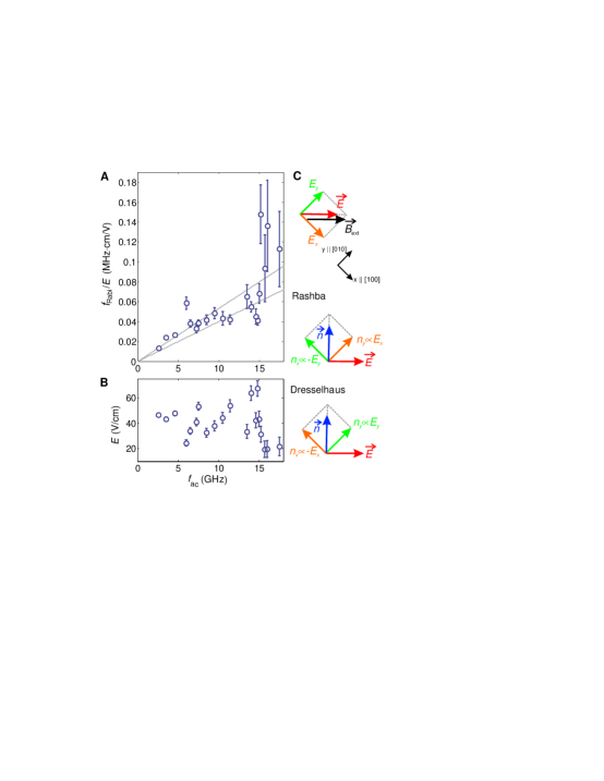
An electric field will periodically and adiabatically displace the electron wave function (see Fig. 1B) by , so the electron spin will feel an oscillating effective field through the dependence of on the position. The direction of can be constructed from the direction of the electric field as shown in Fig. 4C and together with the direction of determines how effectively the electric field couples to the spin. The Rashba contribution always gives , while for the Dresselhaus contribution this depends on the orientation of the electric field with respect to the crystal axis. Given the gate geometry, we expect the dominant electric field to be along the double dot axis (see Fig. 1A) which is here either the or crystallographic direction. For these orientations, the Dresselhaus contribution is also orthogonal to the electric field (see Fig. 4C). This is why both contributions will give and lead to coherent oscillations in the present experimental geometry, where . Note that in [26], a very similar gate geometry was used, but the orientation of was different, and it can be expected that . In that experiment, no coherent oscillations were observed, which is consistent with the considerations here.
An important characteristic of spin-orbit mediated driving is the linear dependence of the effective driving field on the external magnetic field which follows from Eq. 1 and is predicted in [12, 13, 29]. We aim at verifying this dependence by measuring the Rabi frequency as a function of the resonant excitation frequency (Fig. 4A), which is proportional to the external magnetic field. Each point is rescaled by the estimated applied electric field (Fig. 4B). Even at fixed output power of the microwave source, the electric field at the dot depends on the microwave frequency due to various resonances in the line between the microwave source and the gate (caused by reflections at the bonding wires and microwave components). However, we use the photon-assisted-tunneling response as a probe for the ac voltage drop across the interdot tunnelbarrier, which we convert into an electric field amplitude by assuming a typical interdot distance of 100 nm. This allows us to roughly estimate the electric field at the dot for each frequency [17]. Despite the large error bars, which predominantly result from the error made in estimating the electric field, an overall upgoing trend is visible in Fig. 4A.
For a quantitative comparison with theory, we extract the spin-orbit strength in GaAs, via the expression of the effective field perpendicular to for the geometry of this experiment [12]
| (2) |
with the spin-orbit length (for the other definitions see Fig. 1B). Here, for the case with the gate symmetry axis along or respectively. Via , the confidence interval of the slope in Fig. 4A gives a spin-orbit length of m (with a level splitting in the right dot of 0.9 meV extracted from high bias transport measurements). Additional uncertainty in is due to the estimate of the interdot distance and the assumption of a homogenous electric field, deformation effects of the dot potential [15] and extra cubic terms in the Hamiltonian [7]. Still, the extracted spin-orbit length is of the same order of magnitude as other reported values for GaAs quantum dots [18].
Both the observed trend of with and the extracted range for are consistent with our supposition (by elimination of other mechanisms) that spin transitions are mediated by spin-orbit interaction. We note that also for relaxation of single electron spins in which electric field fluctuations from phonons couple to the spin, it is by now well established that the spin-orbit interaction is dominant at fields higher than a few 100 mT [28, 29, 12, 18]. It can thus be expected to be dominant for coherent driving as well.
The electrically driven single spin resonance reported here, combined with the so-called gate based on the exchange interaction between two neighbouring spins [30], brings all-electrical universal control of electron spins within reach. While the gate already operates on sub-nanosecond timescales, single-spin rotations still take about one hundred nanoseconds (the main limitation is photon-assisted-tunneling). Faster operations could be achieved by suppressing photon-assisted-tunneling (e.g. by increasing the tunnel barriers or operating deeper into Coulomb blockade), by working at still higher magnetic fields, by using materials with stronger spin-orbit interaction or through optimized gate designs. Furthermore, the electrical control offers the potential for spatially selective addressing of individual spins in a quantum dot array, since the electric field is produced by a local gate. Finally, we note that the spin rotations were realized at magnetic fields high enough to allow for single-shot read-out of a single spin [31], so that both elements can be integrated in a single experiment.
References and Notes
- [1] D. Awschalom, D. Loss, N. Samarth, Semiconductor Spintronics and Quantum Computation (Springer, 2002).
- [2] C. Poole, Electron Spin Resonance, 2nd ed. (Wiley, New York, 1983).
- [3] B. Simovič et al., Review of Scientific Instruments 77, 064702 (2006).
- [4] F. H. L. Koppens et al., Nature 442, 766 (2006).
- [5] Y. Tokura, W. G. Van der Wiel, T. Obata, S. Tarucha, Phys. Rev. Lett. 96, 047202 (2006).
- [6] Y. A. Bychkov, E. I. Rashba, J. Phys. C 17, 6039 (1984).
- [7] G. Dresselhaus, Phys. Rev. 100, 580 (1955).
- [8] Y. Kato, R. C. Myers, A. C. Gossard, D. D. Awschalom, Nature 427, 50 (2003).
- [9] Y. Kato et al., Science 299, 1201 (2003).
- [10] G. Salis et al., Nature 414, 619 (2001).
- [11] M. Schulte, J. G. S. Lok, G. Denninger, W. Dietsche, Phys. Rev. Lett. 94, 137601 (2005).
- [12] V. N. Golovach, M. Borhani, D. Loss, Phys. Rev. B 74, 165319 (2006).
- [13] L. Levitov, E. Rashba, Phys. Rev. B 67, 115324 (2003).
- [14] S. Debald, C. Emary, Phys. Rev. Lett. 94, 226803 (2005).
- [15] J. Walls, http://arxiv.org/abs/0705.4231 (2007).
- [16] F. H. L. Koppens et al., J. Appl. Phys. 101, 081706 (2007).
- [17] See supporting online material.
- [18] R. Hanson, L. P. Kouwenhoven, J. R. Petta, S. Tarucha, L. M. K. Vandersypen, Rev. Mod. Phys. 79, 1217 (2007).
- [19] A. V. Khaetskii, D. Loss, L. Glazman, Phys. Rev. Lett. 88, 186802 (2002).
- [20] I. A. Merkulov, A. L. Efros, M. Rosen, Phys. Rev. B 65, 205309 (2002).
- [21] A. C. Johnson et al., Nature 435, 925 (2005).
- [22] F. H. L. Koppens et al., Science 309, 1346 (2005).
- [23] J. Baugh, Y. Kitamura, K. Ono, S. Tarucha, Phys. Rev. Lett. 99, 096804 (2007).
- [24] M. S. Rudner, L. S. Levitov, Phys. Rev. Lett. 99, 036602 (2007).
- [25] D. Klauser, W. A. Coish, D. Loss, Phys. Rev. B 73, 205302 (2006).
- [26] E. A. Laird et al., http://arxiv.org/abs/0707.0557 (2007).
- [27] F. H. L. Koppens et al., Phys. Rev. Lett. 99, 106803 (2007).
- [28] S. I. Erlingsson, Y. V. Nazarov, Phys. Rev. B 66, 155327 (2002).
- [29] A. V. Khaetskii, Y. V. Nazarov, Phys. Rev. B 64, 125316 (2001).
- [30] J. R. Petta et al., Science 309, 2180 (2005).
- [31] J. M. Elzerman et al., Nature 430, 431 (2004).
-
1.
We thank L. P. Kouwenhoven, C. Barthel, E. Laird, M. Flatté, I. T. Vink and T. Meunier for discussions; R. Schouten, B. van der Enden and R. Roeleveld for technical assistance and J. H. Plantenberg and P. C. de Groot for help with the microwave components. Supported by the Dutch Organization for Fundamental Research on Matter (FOM) and the Netherlands Organization for Scientific Research (NWO).
Supporting Online Material
- A
-
Supplementary Materials and Methods
- B
-
Supplementary Text
-
B.1
Extraction of Rabi oscillations from magnetic field sweeps
-
B.2
Estimate of the electric field amplitude at the dot
-
B.3
Upper bound on the ac magnetic field amplitude at the dot
-
B.1
- C
-
Supplementary Figures
- D
-
Supplementary References
A Supplementary Materials and Methods
The GaAs/AlGaAs heterostructure from which the sample were made was purchased from Sumitomo Electric. The 2DEG has a mobility of at 77K, and an electron density of , measured at 30 mK with a different device than used in the experiment. Background charge fluctuations made the quantum dot behaviour excessively irregular. The charge stability of the dot was improved considerably in two ways. First, the gates were biased by +0.5 V relative to the 2DEG during the device cool-down. Next, after the device had reached base temperature, the reference of the voltage sources and IV converter (connected to the gates and the 2DEG) were biased by +2 V. This is equivalent to a -2 V bias on both branches of the coplanar stripline (CPS), which therefore (like a gate) reduces the 2DEG density under the CPS. The sample used is identical to the one in reference [1].
Based on transport measurements through the double dot, we can be nearly certain that there were only two electrons present in the double dot. Note however that the addition of two extra electrons in one of the two dots does not affect the manipulation and detection scheme.
The microwave bursts were created by sending a microwave signal generated by a Rohde & Schwarz SMR40 source through either a high isolation GaAs RF switch (Minicircuits ZASWA-2-50DR) for frequencies in the range of 10MHz to 4.6GHz or through two mixers in series (Marki Microwave M90540) for frequencies above 5GHz. The switch and the mixers were gated by rectangular pulses from an arbitrary wave form generator (Tektronix AWG520). The microwave bursts and voltage pulses generated by the marker channel of the same waveform generator were combined (splitter Pasternack PE2064) and applied to the right side gate through a home made bias-tee (rise time 150 ps and a RC charging time of 10ms at 77K).
The measurements were performed in a Oxford Instruments Kelvinox 400 HA
dilution refrigerator operating at a base temperature of 38mK.
B Supplementary Text
B.1 Extraction of Rabi oscillations from magnetic field sweeps
In Fig. 2C we see that at large external magnetic field, the nuclear field fluctuates over a much larger range than , where is the nuclear field experienced by the electron spin when the nuclei are fully polarized and the number of nuclei overlapping with the electron wave function. This made it impossible in the experiment to record a Rabi oscillation at constant . We therefore chose to sweep the external magnetic field through the resonance. We measured a few magnetic field sweeps per microwave burst length and averaged over the max (raw data shown in Fig. S1A)imum current values reached in each sweep.
However, when extracting the Rabi oscillation by looking at the absolute maximum per magnetic field sweep, it is not obvious that the correct Rabi period is found. For instance, a burst which produces a rotation at resonance, gives a tip angle different from away from resonance.
In order to illustrate the effect more fully, Fig. S1B shows a map of the probability for flipping a spin, calculated from the Rabi formula [2] as a function of the detuning away from resonance and the microwave burst length. When taking for each fixed burst length the maximum probability, a saw tooth like trace is obtained (Fig. S1C). Still the positions of the maxima remain roughly at burst lengths corresponding to odd multiples of and the distance between maxima corresponds to the Rabi period.
In addition, we note that every data pixel in Fig. S1A is integrated for about 50ms, so it presumably represents an average over a number of nuclear configurations. This is additionally taken into account in Fig. S1D by averaging each point over a Gaussian distribution of detunings. The width of the distribution used in Fig. S1D corresponds to statistical fluctuations of the nuclear field along the direction of the external magnetic field of mT (at a driving field of mT). This assumes that on top of the large variation of the nuclear field, visible in Fig. 2C, which occurs on a minute time scale, the nuclear field undergoes additional statistical fluctuations on a faster time scale. Taking the maximum in Fig. S1D for each microwave burst length reveals a rather smooth Rabi oscillation (Fig. S1E) with a phase shift [3], and again with the proper Rabi period.
Presumably neither case, with and without averaging over a distribution of detunings, reflects the actual experimental situation in detail. However in the simulation the Rabi period obtained from the periodicity of the maximum probability as a function of the burst length is independent of the width of the gaussian distribution.
Finally, we remark that these conclusions are unchanged when considering the maximum current for each burst length (the current measures parallel spins versus anti-parallel spins) instead of the maximum probability for flipping a single spin. On this basis, we conclude that taking the maximum current value for each burst length gives us a reliable estimate of the Rabi period.
B.2 Estimate of the electric field amplitude at the dot
The electric field generated at the dot by excitation of a gate is difficult to quantify exactly. While we can estimate the power that arrives at the sample holder from the output power of the microwave source and the measured attenuation in the line, the power that arrives at the gate is generally somewhat less (the coax is connected to the gate via bonding wires). In addition, it is difficult to accurately determine the conversion factor between the voltage modulation of the gate and the electric field modulation of the dot. We here estimate the voltage drop across the interdot tunnel barrier via photon-assisted-tunneling (PAT) measurements, and extract from this voltage drop a rough indication of the electric field at the dot.
The leakage current through the double quantum dot in the spin blockade regime as a function of the detuning (defined in Fig. S2A) shows at T a peak at due to resonant transport and a tail for due to inelastic transport (emission of phonons) [4] (Fig. S2B). Excitation of the right side gate induces an oscillating voltage drop across the tunnel barrier between the two dots, which leads to side peaks at away from the resonant peak (Fig. S2C). These side peaks are due to electron tunnelling in combination with absorption or emission of an integer number of photons, a process which is called photon-assisted-tunneling. In the limit where is much smaller than the linewidth of the states ( is the tunnel rate) the individual sidepeaks cannot be resolved, whereas for higher frequencies they are clearly visible (see Fig. S2D).
More quantitatively we describe PAT by following reference [5]. An ac voltage drop across the interdot tunnel barrier modifies the tunnel rate through the barrier as . Here, and are the tunnel rates at energy E with and without ac voltage, respectively; is the square of the nth order Bessel function of the first kind evaluated at , which describes the probability that an electron absorbs or emits photons of energy equal to (with the electron charge). Fig. S1E shows the current calculated from this model including a lorentzian broadening of the current peaks. A characteristic of the -th Bessel function , important here, is that it is very small for (i.e. when ) and starts to increase around , implying that the number of side peaks is approximately . This results in a linear envelope visible in Fig. S1E.
We extract as the width of the region with non-zero current measured at fixed microwave frequency and amplitude . Instead of this width, we can take equivalently the number of side peaks times (this is possible at frequencies high enough such that individual side peaks are resolved). A reasonable estimate of the error made in determining is . Another method to extract is to determine the slope of the envelope (for which a threshold current needs to be chosen) of the PAT response (see Fig. S2D). Varying the threshold gives a spread in the slope which defines the error of this method. We note that within the error bars both methods give the same result.
In order to estimate from the amplitude of the oscillating electric field at the
dot, , we assume that this voltage drops linearly over the distance between the two dot centers (a rough
approximation), which is approximately 100 nm. This estimate is used in Fig. 4A in the main text, and in
the approximate determination of the spin orbit length. Note that the uncertainty in this estimate of the spin-orbit length only affects the overall scaling in Fig. 4A, but not the fact that there is an up-going trend.
B.3 Upper bound on the ac magnetic field amplitude at the dot
The oscillating gate voltage produces an oscillating electric field at the dot. Here we determine an upper bound on the oscillating magnetic field that is unavoidably generated as well. Since the distance from the gate to the dot is much smaller than the wavelength (20 GHz corresponds to 1.5 cm), we do this in the near-field approximation, where magnetic fields can only arise from currents (displacement currents or physical currents).
An oscillating current can flow from the right side gate to ground via the 2DEG, the coplanar stripline [1], or the neighbouring gates (all these elements are capacitively coupled to the right side gate). We first consider the case of the stripline. The right side gate is about 100nm wide and overlaps with the coplanar stripline over a length of about 10 m, giving an overlap area of . The gate and stripline are separated by a 100 nm thick dielectric (calixerene [6], ), which results in a capacitance of 0.6 fF. For a maximum voltage of 10 mV applied to the right side gate and a microwave frequency of 20 GHz, this gives a maximum displacement current through this capacitor of A. This is an upper bound as we neglect all other impedances in the path to ground. Even if this entire current flowed at a distance to the dot of no more than 10 nm (whether in the form of displacement currents or physical currents), it would generate a magnetic field of only mT, more than two orders of magnitude too small to explain the observed Rabi oscillations. In reality, the displacement current is distributed along the length of the gate, and most of the current through the gate and stripline flows at a distance very much greater than 10 nm from the dot, so is still much smaller than 0.02 mT. The maximum magnetic field resulting from capacitive coupling to the other gates and to the 2DEG is similarly negligible.
It is also instructive to compare the power that was applied to the gate for electric excitation of the spin with the power that was applied to the microfabricated stripline for magnetic excitation [1]. For the shortest Rabi periods observed here (220 ns), the power that arrived at the sample holder was less than dBm (the output power of the microwave source minus the attenuation of the microwave components in between source and sample holder, measured at 6 GHz – at higher frequencies, the attenuation in the coax lines will be still higher). In order to achieve this Rabi frequency through excitation of the stripline, more than 100 times more power ( dBm) was needed directly at the stripline [1].
The upper bounds we find for the oscillating magnetic field generated along with the electric field are thus much smaller than the field needed to obtain the measured Rabi frequencies of a few MHz. We therefore exclude magnetic fields as a possible origin for our observations.
C Supplementary Figures
D Supplementary References
References and Notes
- [1] F. H. L. Koppens, C. Buizert, K.-J. Tielrooij, I. T. Vink, K. C. Nowack, T. Meunier, L. P. Kouwenhoven and L. M. K. Vandersypen, Nature 442, 766 (2006).
- [2] C. Poole, Electron Spin Resonance, 2nd ed. (Wiley, New York, 1983).
- [3] F. H. L. Koppens, D. Klauser, W. A. Coish, K. C. Nowack, L. P. Kouwenhoven, D. Loss and L. M. K. Vandersypen, Phys. Rev. Lett. 99, 106803 (2007).
- [4] F. H. L. Koppens, J. A. Folk, J. M. Elzerman, R. Hanson, L. H. W. van Beveren, I. T. Vink, H. P. Tranitz, W. Wegscheider, L. P. Kouwenhoven and L. M. K. Vandersypen, Science 309, 1346 (2005).
- [5] T. H. Stoof and Y. V. Nazarov, Phys. Rev. B 53, 1050 (1996).
- [6] A. Holleitner, Applied Physics Letters 82, 1887 (2003).