Fast Single-Charge Sensing with an rf Quantum Point Contact
Abstract
We report high-bandwidth charge sensing measurements using a GaAs quantum point contact embedded in a radio frequency impedance matching circuit (rf-QPC). With the rf-QPC biased near pinch-off where it is most sensitive to charge, we demonstrate a conductance sensitivity of with a bandwidth of 8 MHz. Single-shot readout of a proximal few-electron double quantum dot is investigated in a mode where the rf-QPC back-action is rapidly switched.
Mesoscopic charge sensors such as the single-electron transistor (SET) Fulton and Dolan (1987) and the quantum point contact (QPC) Field et al. (1993) are at the heart of many readout technologies for quantum information processing. As electrometers, their intrinsic sensitivity Devoret and Schoelkopf (2000); Korotkov (1999) provides efficient measurement with detector noise close to the minimum allowed by quantum mechanics Clerk et al. (2003). When combined with high-bandwidth operation, these devices are attractive for application in metrology Bylander et al. (2005); Fujisawa et al. (2006), single photon detection Komiyama et al. (2000), and as non-invasive charge probes at the nanoscale Lu et al. (2003); DiCarlo et al. (2004); Biercuk et al. (2006).
Combining sensitivity with fast operation is challenging because of the large time of the detector resistance ( 50 k) and shunt capacitance of wire between the cold stage of a cryostat and room-temperature electronics (hundreds of pF). Nevertheless several demonstrations of single-electron detection have been reported with bandwidths in the tens of kHz Vandersypen et al. (2004); Gustavsson et al. (2006); Amasha et al. (2006). An approach Schoelkopf et al. (1998) that circumvents the difficulty of wiring capacitance uses an impedance matching network on resonance to transform the high resistance of the detector towards the = 50 characteristic impedance of a transmission line. Changes in device resistance modulate the reflected or transmitted Fujisawa and Hirayama (2000) power of a radio frequency (rf) carrier, tuned to the resonance frequency. Application of this reflectometry technique to aluminum based SETs has demonstrated charge sensing Lu et al. (2003), near quantum-limited sensitivity Devoret and Schoelkopf (2000); Aassime et al. (2001), and bandwidths above 100 MHz Schoelkopf et al. (1998).
In this Letter, we extend rf reflectometry to a semiconductor quantum point contact. We describe the reflectometer circuit in detail and explore its performance as a fast, cryogenic charge sensor, demonstrating single-electron sensing with 8 MHz bandwidth. In the regime of operation, intrinsic shot noise of the QPC makes up approximately 80% of the total system noise. Previous work Qin and Williams (2006); Muller (2007) has demonstrated modulation of rf power by a point contact operated as a voltage-controlled resistor. Here, we demonstrate application of the QPC as a fast charge sensor by performing charge-state readout of an integrated double quantum dot Petta et al. (2005) with fixed total charge. In addition, we present single-shot measurements of the double dot in a mode where the rf-QPC carrier is rapidly switched, modulating the measurement back-action on a time-scale of 50 ns.
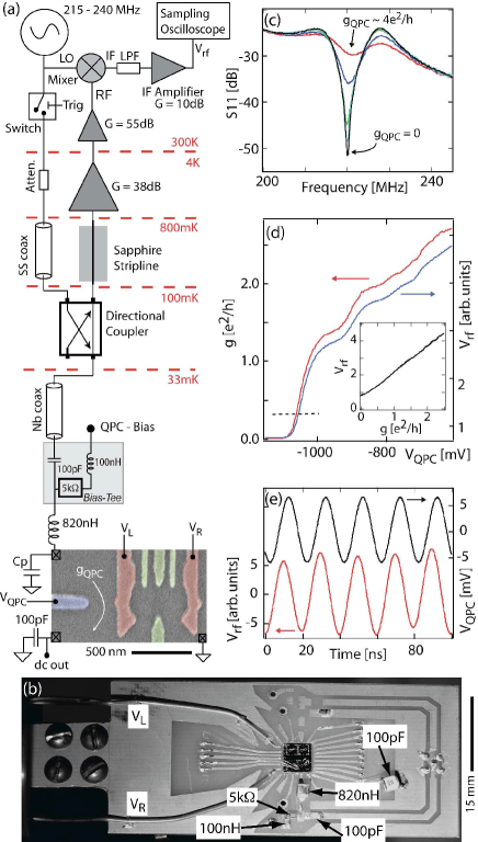
The device, shown in Fig. 1(a), consists of a GaAs/Al0.3Ga0.7As heterostructure with two dimensional electron gas (density 2 10 15m-2, mobility 20 m2/Vs) 100 nm below the surface. Ti/Au top gates define a few-electron double dot with proximal QPC.
An impedance matching network is formed by a chip inductor designed (a) (820 nH) and the parasitic capacitance of the bond pads and wires ( 0.63 pF) [see Fig. 1]. Changes in modulate the rf carrier power reflected from the matching network at resonance, as shown in Fig. 1(c). Demodulation is performed at room temperature by mixing the reflected designed (a) and amplified rf signal with a local oscillator (LO) (HP8647A) at the carrier frequency to yield an intermediate frequency (IF) signal, which is low-pass filtered (3dB corner frequency is 10 MHz) to remove the sum component and then further amplified (SRS SR560) to yield a voltage, , proportional to .
Measurements were made in a dilution refrigerator with electron temperature 120 mK, measured by noise thermometry Spietz et al. (2006). The sample is mounted on a circuit board designed (a) which has 20 dc and 4 high frequency (GHz) coax lines together with 50 striplines for reflectometry. The system noise temperature, , determined by signal losses and the noise contribution of both the cryogenic (Quinstar) and room-temperature (Miteq AU-1565) amplifiers, was estimated to be 3.5 K by using the QPC shot noise to calibrate the gain of the system Aassime et al. (2001). An on-board bias-tee enables simultaneous reflectometry and dc transport [Fig. 1(d)]. With and matching inductance reduced to 550 nH, the rf-QPC operates in the undercoupled regime Roschier et al. (2004) with a bandwidth of approximately 100 MHz determined by the rise-time of in response to a 50 MHz bias applied to a gate, as shown in Fig. 1(e).
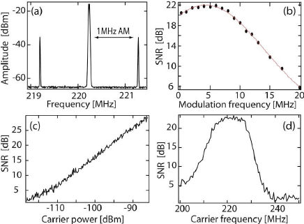
The sensitivity of the rf-QPC was determined by applying a 1 MHz voltage = 0.7 mV to the right gate [see Fig. 1(a)] to modulate the QPC conductance by 0.018 . Figure 2(a) shows the resulting amplitude modulation (AM) spectrum (prior to demodulation), with sidebands symmetric about the carrier. The signal-to-noise ratio (SNR) is given by the ratio of the height of a sideband to the noise floor in a bandwidth . This SNR gives a conductance sensitivity , where the factor accounts for power collected from both sidebands, of . This sensitivity allows, for instance, a conductance change to be measured with unity SNR in = 500 ns. Above 8 MHz, the -factor ( 15) of the impedance matching circuit limits the sensitivity as shown in Fig. 2(b). The SNR increases with applied carrier power [Fig. 2(c)] up to the energy scale set by the one-dimensional sub-band spacing (typically several mV). A source-drain bias of 1 mV requires a carrier power of approximately -70dBm. For the charge sensing measurements described below, carrier power was set to -75 dBm. For this power, 80% of the output noise is the intrinsic shot noise of the QPC. Figure 2(d) shows the dependence of the sideband SNR on carrier frequency, consistent with reflected power measurements [Fig. 1(c)].
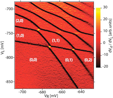
We demonstrate the operation of the rf-QPC by detecting single-electron changes is charge configuration of a double quantum dot in the few-electron regime. For this demonstration, the QPC was biased on the steep edge of a conductance riser at , where the conductance is a sensitive function of the local electrostatic potential [see Fig. 1(d)]. Figure 3 shows as a function of gate voltages and , which control the number of electrons in the left and right dots. Stable charge configurations of the double dot correspond to the red colored regions with labels (n,m) indicating the electron occupancy on the left and right dot. Charge transitions appear in the derivative of as black and yellow lines.
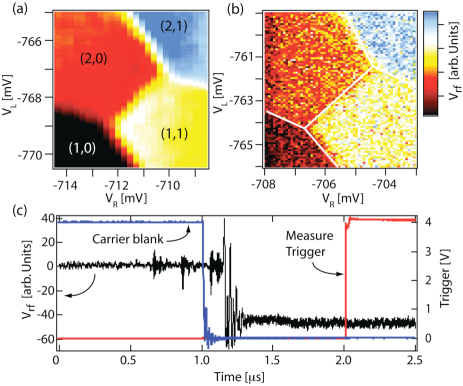
Focusing on the (2,0)-(1,1) transition, Fig. 4(a) shows as a function of and with each data point averaged 32 times. In the device studied, a change in QPC conductance of ( 0.003 ) is associated with an electron transition between (1,1) and (2,0). Using the measured conductance sensitivity , we find a charge sensitivity of , i.e., 5 s is needed to perform charge readout with SNR of unity for this device.
Coupling rf power to the QPC has two effects on the double dot. Firstly, an intrinsic back-action in the form of shot noise in the QPC produces radiation that can drive transitions between double dot energy levels Gustavsson et al. (2007). Secondly, at high rf carrier power we observe some distortion in the charge stability plot [Fig. 4(a)] which is likely due to heating Vandersypen et al. (2004) and capacitive coupling between the oscillating QPC source-drain bias and top gates. In some applications it may be useful to eliminate the back-action of the QPC during certain phases of the duty cycle. This can be done by rapidly applying the carrier power only during a measurement using a solid-state rf-switch designed (c) [see Fig. 1(a)] to blank the carrier power, as shown in Fig. 4(c). The -factor of the matching network sets a time scale of 50 ns for the QPC to enter the measurement phase. After waiting 1 s from the initial un-blank switch, a digitizing scope (Agilent DSO8104A) is triggered to acquire data for time . In Fig. 4(b) we show single-shot measurements in this switched back-action mode, sampling for = 60 s during the measurement phase. The value of each pixel is the average of over 60 s, which yields an SNR of 4, in reasonable agreement with the charge sensitivity measured at 1 MHz in the frequency domain described above.
High-fidelity readout in the present device is limited by the small coupling between the QPC and the double dot, a device parameter that can be increased considerably by improved sample design, as demonstrated, for example, in Ref. Amasha et al. (2006). The rf-QPC may also be useful in detecting small changes in mesoscopic capacitance Cheong et al. (2002) that alter its resonance frequency and in the simultaneous measurement of many rf-QPCs using multiplexing techniques Stevenson et al. (2002); Buehler et al. (2004).
We thank M. J. Biercuk, L. DiCarlo, E. A. Laird, D. T. McClure, and Y. Zhang for technical contributions. We especially thank J. R. Petta for experimental contributions including fabrication of the sample used. This work was supported by DARPA, DTO, NSF-NIRT (EIA-0210736), and Harvard Center for Nanoscale Systems. Research at UCSB supported in part by QuEST, an NSF Center.
References
- Fulton and Dolan (1987) T. A. Fulton and G. J. Dolan, Phys. Rev. Lett. 59, 109 (1987).
- Field et al. (1993) M. Field et al., Phys. Rev. Lett. 70, 1311 (1993).
- Korotkov (1999) A. N. Korotkov, Phys. Rev. B. 60, 5737 (1999).
- Devoret and Schoelkopf (2000) M. H. Devoret and R. J. Schoelkopf, Nature (London) 406, 1039 (2000).
- Clerk et al. (2003) A. A. Clerk, S. M. Girvin, and A. D. Stone, Phys. Rev. B. 67, 165324 (2003).
- Bylander et al. (2005) J. Bylander, T. Duty, and P. Delsing, Nature (London) 434, 361 (2005).
- Fujisawa et al. (2006) T. Fujisawa, et al., Science 312, 1634 (2006).
- Komiyama et al. (2000) S. Komiyama, et al., Nature (London) 403, 405 (2000).
- Lu et al. (2003) W. Lu, et al. Nature (London) 423, 422 (2003).
- DiCarlo et al. (2004) L. DiCarlo, et al., Phys. Rev. Lett. 92, 226801 (2004).
- Biercuk et al. (2006) M. J. Biercuk, et al., Phys. Rev. B. 73, 201402(R) (2006).
- Vandersypen et al. (2004) L. M. K. Vandersypen et al., App. Phys. Lett. 85, 4394 (2004).
- Gustavsson et al. (2006) S. Gustavsson, et al., Phys. Rev. Lett. 96, 076605 (2006).
- Amasha et al. (2006) S. Amasha, et al., (unpublished) arXiv:0607110 (2006).
- Schoelkopf et al. (1998) R. J. Schoelkopf, et al., Science 280, 1238 (1998).
- Fujisawa and Hirayama (2000) T. Fujisawa and Y. Hirayama, App. Phys. Lett. 77, 543 (2000).
- Aassime et al. (2001) A. Aassime, et al., App. Phys. Lett. 79, 4031 (2001).
- Qin and Williams (2006) H. Qin and D. A. Williams, App. Phys. Lett. 88, 203506 (2006).
- Muller (2007) T. Müller, et al., 28th Int. Conf. on the Physics of Semincond. Proc. AIP., 893, 1113 (2007).
- Petta et al. (2005) J. R. Petta, et al., Science 309, 2180 (2005).
- designed (a) CoilCraft 1206CS-821XL.
- designed (a) Mini-Circuits mixer ZP-3MH and directional coupler ZEDC-15-2B a
- Spietz et al. (2006) L. Spietz, R. J. Schoelkopf, and P. Pari, App. Phys. Lett. 89, 183123 (2006).
- designed (a) The circuit board was designed to minimize parasitic capacitance and cross-coupling using Sonnet Suites software. a
- Roschier et al. (2004) L. Roschier, et al., J. App. Phys. 95, 1274 (2004).
- Gustavsson et al. (2007) S. Gustavsson, et al., (unpublished) arXiv:0705.3166 (2007).
- designed (c) Mini-Circuits ZASWA-2-50DR. c
- Cheong et al. (2002) H. D. Cheong, et al., App. Phys. Lett. 81, 3257 (2002).
- Stevenson et al. (2002) T. R. Stevenson, et al., App. Phys. Lett. 80, 3012 (2002).
- Buehler et al. (2004) T. M. Buehler, et al., J. Appl. Phys. 96, 4508 (2004).