Muon-fluorine entangled states in molecular magnets
Abstract
The information accessible from a muon-spin relaxation experiment is often limited since we lack knowledge of the precise muon stopping site. We demonstrate here the possibility of localizing a spin polarized muon in a known stopping state in a molecular material containing fluorine. The muon-spin precession that results from the entangled nature of the muon-spin and surrounding nuclear spins is sensitive to the nature of the stopping site and we use this property to identify three classes of site. We are also able to describe the extent to which the muon distorts its surroundings.
pacs:
76.75.+i, 75.50.Xx, 61.18.Fs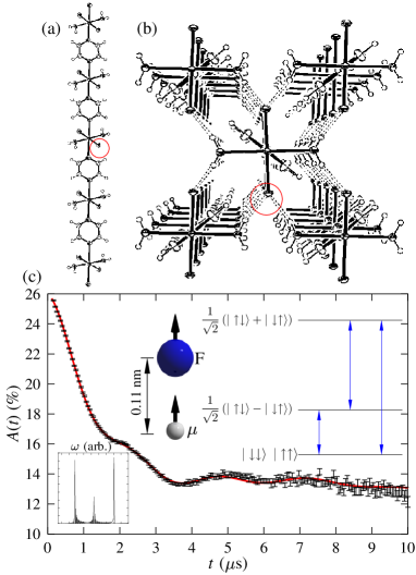
Muon-spin relaxation (SR) continues to provide insights into the nature of magnetic materials, superconductors, semiconductors, soft matter and chemical reactions steve . The technique involves stopping spin polarized muons in a target sample where the muons probe the distribution of local magnetic fields across the muon stopping sites. Despite its successes, two concerns are sometimes raised. The first is that the exact muon stopping site in a material is, in general, not precisely known, introducing some uncertainty in the determination of the local spin structure. This is especially applicable in anisotropic or chemically complex materials where a number of different candidate stopping sites exist. A second objection is that it is not possible to quantify the degree to which the presence of the charged muon distorts its surroundings and hence to estimate the modification of superexchange pathways that could, in principle, affect the local spin structure. Here we show that in addition to the magnetic behavior usually probed by SR, the entangled states of spin and 19F nuclear spins allow the accurate determination of the muon site in a class of novel fluorinated molecular magnets, along with an estimate of the distortion introduced by the presence of the probe particle.
Localized muons in solids often interact with their environment via dipole-dipole coupling. In many cases the large number of spin centres surrounding the muon allow the use of the local magnetic field (LMF) approximation, where the muon spin interacts with the net local magnetic field at the muon site via the Hamiltonian , where is the muon gyromagnetic ratio. For the commonly encountered case of the muon response to an ensemble of randomized static local fields, the LMF model gives the Kubo-Toyabe function hayano , which is well approximated by a Gaussian function at early times. Occasionally, however, the muon is found to interact strongly with a small number of spin centres through dipole coupling lord ; celio , a process which is described by the Hamiltonian
| (1) |
where is the vector linking spins and , which have gyromagnetic ratios . This strong interaction is found most often in materials containing fluorine, for two reasons: fluorine is the most electronegative element, causing muons to localise in its vicinity and fluorine occurs with a single isotope (19F) with an nuclear spin, giving rise to a strong SR signal as a result of the interaction (see below). For example, in most insulating metal fluorides brewer the muon sits midway between two fluorine ions forming a strong linear “hydrogen bond” with an F–F separation of nm, which is approximately twice the fluorine ionic radius. This stopping state (the so-called F––F) is similar to the centre observed in alkali halides, which is often treated as a molecule-in-a-crystal defect hayes , where the host weakly perturbs the molecular ion.
The fact that the spins are not initially in an eigenstate of the Hamiltonian in Eq. (1) causes a time dependence of the system’s total wavefunction, visualised classically as spontaneous precession of all spin species. The observed property in SR is the polarization of the muon ensemble along a quantization axis , which is given by roduner
| (2) |
where is the number of spins, and are eigenstates of the total Hamiltonian and is the Pauli spin matrix corresponding to the quantization direction.
These considerations suggest that, in compounds containing fluorine ions, muons might be localized in known positions near fluorines. The muon and fluorine spins then become entangled causing the spins to evolve via the Hamiltonian in Eq.(1) and the sensitivity of the interaction to the relative positions of the spin centres allows the spin configuration and stopping site to be determined. This is indeed the case in a novel class of fluorine-containing molecular magnets. The stopping states, however, are more complex than the linear F–-F molecular ion previously observed in many inorganic insulating fluorides brewer .
Molecular magnets are self assembled materials which are formed through bridging paramagnetic cation centres (such as Cu2+ in the compounds studied here (see Table 1)) with organic ligands. These materials often possess low-dimensional (i.e. 2D, 1D) structural motifs and correspondingly display low-dimensional magnetic properties steveandfrancis . Our recent experiments on such systems have shown that muons are uniquely sensitive to the presence of long-range magnetic order lancaster . Below the antiferromagnetic transition at we observe oscillations in the time dependence of the muon polarization (the “asymmetry” steve ) which are characteristic of a quasi-static local magnetic field at the muon stopping site. In the LMF model, this local field causes a coherent precession of the spins of those muons for which a component of their spin polarization lies perpendicular to this local field (expected to be 2/3 of the total spin polarization for a powder sample). The frequency of the oscillations is given by , where is the muon gyromagnetic ratio ( MHz T-1) and is the average magnitude of the local magnetic field at the th muon site. Above the character of the measured spectra changes considerably and we observe lower frequency oscillations characteristic of the dipole interaction of the muon and the 19F nucleus. The Cu2+ electronic moments, which dominate the spectra for , are no longer ordered in the paramagnetic regime, and fluctuate very rapidly on the muon time scale. They are therefore motionally narrowed from the spectra, leaving the muon sensitive to the quasistatic nuclear magnetic moments. The signal arising from F– states persist in these materials to temperatures well above 100 K.
In fluorinated materials, where the muon-spin is relaxed through interaction with nuclear moments, we expect two contributions to the SR spectra. The first is from muons that strongly couple to fluorine nuclei, which give rise to contributions derived from Eq. (2). Note that since our measurements are carried out on powder samples, also includes the effect of angular averaging. The second contribution is from those muons weakly coupled to a large number of nuclei, leading to Gaussian relaxation in the LMF model, as described above. Above the critical temperature , spectra were found to be well described by the resulting polarization function
| (3) |
where is the signal arising from the sample, , and accounts for those muons that stop in the sample holder or cryostat tails.
Below we discuss experimental resultsexperiment for three molecular materials where stopping states arise that are different from the conventional F––F state and exemplify three distinct classes of implanted muon state.
Case I: Interaction with a single fluorine. The compound CuF2(H2O)2(pyz) manson is formed from CuF2O2N2 octahedra linked with pyrazine bridges along the -direction to form linear chains (Fig. 1(a)). Extensive hydrogen bonding interactions tether the chains into the 3D network shown in Fig. 1(b). The material undergoes an AFM transition at K below which oscillations in the muon asymmetry are observed manson . ZF SR spectra measured on CuF2(H2O)2(pyz) above are shown in Fig. 1(b) where we see slow, heavily damped oscillations characteristic of F– dipole coupled states. The spectra are most successfully modelled by assuming the muon is strongly coupled with a single F spin, localized a distance nm away from a fluorine nucleus. The resulting energy level structure and allowed transitions for this scenario are shown inset in Fig. 1(c). The F– spin system consists of three distinct energy levels with three allowed transitions between them giving rise to the distinctive three-frequency oscillations observed (inset Fig. 1c). The signal is described by a polarization function where , and . The transition frequencies (shown in Fig. 1(c)) are given by where , and is the F– separation. The resulting fit is shown in Fig. 1(c) using the parameters listed in Table 1.
| CuF2(H2O)2(pyz) | 0.43 | 0.36 | 0.57 | 0.56 | 1.2 | 1.6 |
|---|---|---|---|---|---|---|
| CuNO3(pyz)2PF6 | 0.65 | 0.24 | 0.35 | 0.45 | 2.2 | 4.1 |
| Cu(HF2)(pyz)ClO4 | 0.73 | 0.24 | 0.27 | 0.43 | 2.2 | 3.9 |
We note first that the strong interaction of the muon and a single F is unusual. However, a muon stopping site between two fluorines is probably made energetically unfavourable due to the presence of the protons on the H2O groups which are hydrogen bonded to the fluorines (and stabilize the solid). In this material the smallest F–F distance (between adjacent chains) is 0.34 nm and a position midway between these two fluorines invariably lies very close ( nm) to the protons on a H2O group. We further exclude a muon site in CuF2(H2O)2pyz where the muon is bonded to F but sits near the protons on the H2O groups since fits to such a configuration are not able to account for the measured data. It is more probable that the muon’s separation from the F ion is not precisely in the - plane, but rather has a small component in the direction, taking it closer to the electron density on the aromatic rings. We note further that we have also observed coupling of the muon to a single F in the polymer PVDF (–(CH2CF2)n–) below the polymer glass transition me_unpublished . This demonstrates that this stopping state is not unique.
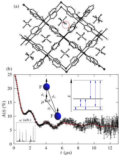
Case II: Crooked F-F bond with the PF ion. The quasi 2D compound [Cu(NO3)(pyz)2]PF6 turnbull ; woodward is formed from infinite 2D sheets of [Cu(pyz)2]2+ lying in the plane. These are linked along the -direction by NO ions. The PF anions occupy the body-centred positions within the pores. The PF anion has a regular octahedral geometry with a P–F distance of 0.157 nm.
Our measurements show that this material magnetically orders below K. Above we again observe a signal from dipole coupling. An example spectrum measured above is shown in Fig. 2. Although one would expect the muon to localise near a PF6 anion, it is not clear a priori how many fluorine centres will be strongly coupled to the muon spin. Modelling the spectra reveals that two fluorine spins interact with the , but not via the linear F––F. Instead we find the F––F bond angle to be with F– lengths nm and nm. The F–F distance, which is 0.22 nm in the unperturbed material, lengthens to 0.25 nm. This configuration is shown inset in Fig. 2. A fit to Eq. 3 resulted in the parameters listed in Table 1 and is shown in Fig. 2. It should also be expected that other materials containing F ions (Sb or As) will have stopping states of this type.
Case III: Interaction with the HF ion. The series of coordination polymers [Cu(HF2)(pyz)2] are formed from infinite 2D sheets of [Cu(pyz)2]2+ in the plane (as in the case of [Cu(NO3)(pyz)2]PF6 above). These are connected along the -axis by linear HF anions to form a pseudo-cubic network. Small tetrahedral or octahedral anions occupy the body centred positions in the pseudo-cubic pores manson2 .
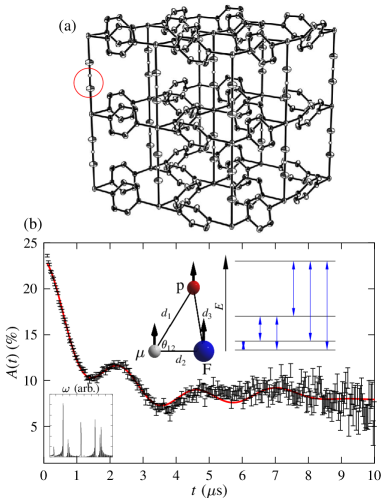
An example spectrum measured above K for [Cu(HF2)(pyz)2]ClO4 is shown in Fig. 3(b). In this case we would expect the muon to localize near the HF anion. The spectrum obtained is qualitatively similar to that expected for the interaction of a muon with a single fluorine ion. However, the best fit is obtained if a third spin centre is included. For the tightly bound HF2 ion we might expect this third centre to be that of the nearest proton (see inset Fig. 3(b)). This configuration is found to fit the data successfully yielding a F– distance of nm, a – distance of nm and a F––p angle of . The p–F distance , which is 0.11 nm in the unperturbed system, is found to be increased to nm in the presence of the muon. The resulting fit to Eq. (3) results in the fitting parameters given in Table 1 and is shown in Fig. 3(b).
In addition we note that no dipole-dipole signal is detected from muons stopping near the BF ion; measurements on Cu(pyz)2(BF and Cu(C5H6NO)6(BF4)2 me_unpublished do not show a F– dipole-dipole signal, while measurements on [Cu(HF2)(pyz)2]BF4 manson2 show the signal from the HF ion described above.
In the conventional F––F case the F atoms may each shift by large distances ( Å) from their equilibrium positions towards the brewer , demonstrating that the muon introduces a non-negligible local distortion in the material. If however, by analogy with the defect center in alkali halides hayes , the F––F complex acts like an independent molecule in the crystal, the distortion in the other ion positions will be much less significant than the distortion of the two F- ions. The centre analogy will be less accurate in cases I-III described above, where the non-linear bonds demonstrate that the muon stopping state cannot be regarded as separate from its surroundings. In these cases the tightly bound nature of the fluorine-containing complexes prevents an independent quasi-molecular impurity from forming.
We have presented three examples of the F– stopping states in molecular materials. The inherently quantum mechanical interaction of the muon spin leads to entangled states involving the surrounding nuclei and has allowed a characterization of the muon stopping state and facilitates a quantitative estimate of the degree to which the muon distorts its surroundings. These results demonstrate that the introduction of fluorine ions in molecular magnets can provide “traps” for muons, so that the local spin structure in such systems can be probed from well characterized muon sites.
Part of this work was carried out at the ISIS facility, Rutherford Appleton Laboratory, UK. This work is supported by the EPSRC (UK). T.L. acknowledges support from the Royal Commission for the Exhibition of 1851. J.L.M. acknowledges an award from Research Corporation. Work at Argonne National Laboratory is sponsored by the U. S. Department of Energy, Office of Basic Energy Sciences, Division of Materials Sciences, under Contract DE-AC02-06CH11357. We thank A.M. Stoneham for useful discussions.
References
- (1) S.J. Blundell, Contemp. Phys. 40, 175 (1999).
- (2) R.S. Hayano et al., Phys. Rev. B 20, 850 (1979).
- (3) J.S. Lord, S.P. Cottrell and W.G. Williams, Physica B 289, 495 (2000).
- (4) M. Celio and P.F. Meier, Hyp. Int. 17-19, 435 (1983).
- (5) J.H. Brewer et al., Phys. Rev. B 33, 7813 (1986).
- (6) W. Hayes and A. M. Stoneham, Defects and Defect Processes in Nonmetallic Solids (Dover, New York, 2004).
- (7) E. Roduner and H. Fischer, Chem. Phys. 54, 261 (1981).
- (8) S. J. Blundell and F. L. Pratt, J. Phys. Condens. Matter 16, R771 (2004).
- (9) T. Lancaster et al., Phys. Rev. B, 73, 020410(R) (2006).
- (10) Zero field (ZF) SR measurements were made on the MuSR instrument at the ISIS facility. Powder samples were packed in 25 m Ag foil and mounted on a Ag backing plate inside an Oxford instruments sorption cryostat; http://www.isis.rl.ac.uk/muons/users/equipment/index.htm.
- (11) J.L. Manson et al., unpublished.
- (12) M.M. Turnbull et al., Mol. Cryst. and Liq. Cryst. 335, 245 (1999).
- (13) F.M. Woodward et al. Inorg. Chem. 46 4256 (2007).
- (14) J.L. Manson et al. Chem. Comm. 4894 (2006).
- (15) T. Lancaster et al. unpublished data.