Bistability in superconducting rings containing an inhomogeneous Josephson junction
Abstract
We investigate the magnetic response of a superconducting Nb ring containing a ferromagnetic PdNi Josephson junction and a tunnel junction in parallel. A doubling of the switching frequency is observed within certain intervals of the external magnetic field. Assuming sinusoidal current-phase relations of both junctions our model of a dc-SQUID embedded within a superconducting ring explains this feature by a sequence of current reversals in the ferromagnetic section of the junction in these field intervals. The switching anomalies are induced by the coupling between the magnetic fluxes in the two superconducting loops.
pacs:
85.25.DqA Superconducting Quantum Interference Device (SQUID) consists of a superconducting loop interrupted by one (rf SQUID), or two (dc SQUID) Josephson junctions. The magnetic moment of rf SQUIDs and the critical current of dc SQUIDs are periodic functions of the magnetic flux enclosed by the loop. In most cases, the periodicity is given by the magnetic flux quantum . This is a consequence of the gauge-invariant connection between and the phase difference across the junction(s) via the current-phase relation (CPR) . Under certain conditions, the CPR of the junction(s) is not a simple sine, but can contain higher harmonics: , where the coupling coefficients quantify the relative strength of processes with a coherent transfer of Cooper-pairs golubov . In some cases, the first order coefficient can even vanish, for instance, in asymmetric degree grain boundary junctions in d-wave symmetry superconductors mannhart ; lindstrom , in out of equilibrium SNS junctions baselmans and for ballistic SFS junctions at the - transition radovic1 ; radovic2 . The remaining second order coefficient will result in a doubling of the frequency in the interference pattern. Although, a frequency doubling has been observed experimentally sellier , its origin is still under debate, since there are also dynamic effects in inhomogeneous junctions, which can lead to this effect frolov2 .
Recently, it was observed that the critical current of high temperature superconductor dc-SQUIDs shows a periodicity in certain sections of the interference pattern lindstrom . To explain this observation it was suggested that the random faceting of the grain-boundary induces a distribution of 0 and couplings along the junction. For some particular values of the applied magnetic field the first order coupling of the overall junction is zero, allowing second order coupling to be dominant. A similar effect has been also measured in the multi terminal transport of a 2-dimensional electron gas connected to a superconducting loop klapwijk .
Here we report on a different material system, showing a similar phenomenology and suggest an alternative interpretation of this phenomenon. We study the magnetic response of an rf SQUID where the junction is inhomogeneous and formed by the parallel connection of a conventional () Josephson junction and a ferromagnetic junction. By measuring the total flux in the SQUID while increasing the external magnetic field , we mostly observe a -periodic penetration of flux quanta into the loop, every time the critical current of the junction is exceeded. However, for some values of the external magnetic field we find a doubling of the switching frequency. The proposed model explains this effect in terms of a bistability of the supercurrent in the -junction for certain values of the applied magnetic field. Our double SQUID model successfully explains the magnetic field and temperature dependence of our observations, although the CPR of both junctions is assumed to be purely sinusoidal.
We use Nb as the superconductor and dilute PdNi as the ferromagnet for our SFS junctions. To pattern the loops, we use a robust Si3N4/PES mask system for the shadow evaporation. The PES (polyether sulfone) forms a highly thermostable sacrificial layer dubos . The 60 nm thick Si3N4 was deposited by plasma enhanced chemical vapor deposition on top of the PES and provides sufficient mechanical stability to resist the large stresses created by the Nb film. After patterning the mask by electron beam lithography and reactive ion etching using CHF3, the Si3N4 mask was underetched by an isotropic oxygen-plasma. The undercut can have a value of up to 1 m. Evaporation of 40 nm of Nb and 10 nm of PdNi under different angles provides the desired superconducting loops with an integrated SFS planar junction, as illustrated by a scanning electron micrographs of a sample in Figs. 1a and b. In Figs. 1c and d the equivalent schematics are shown. The thickness of the PdNi film was chosen to produce a junction close to the 0- crossover kontos1 . A 10% misalignment of the sample during evaporation of the second Nb-layer resulted in an overlap of the two Nb-films without PdNi-interlayer, as indicated by the arrow in Fig. 1b. Strong gettering of residual gas by the Nb during evaporation of PdNi results in a rather transparent tunneling contact between the two Nb-films in this area, as a second Josephson junction.

We have placed the sample on top of the active area of a micron-sized Hall-sensor in order to detect the magnetic response bauer ; geim . The Hall-sensor is realized in a semiconductor heterostructure having the electron density of and the mobility of . We achieve a sensitivity of roughly to depending on the sensor current. For our loop dimensions of approximately , the magnetic flux quantum corresponds to a magnetic field of about .
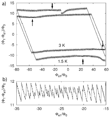
Upon sweeping the external magnetic field, circulating supercurrents in the loops are generated. The resulting flux in the loop, , induces a flux-periodic contribution to the Hall voltage across the Hall sensor, while the contribution of the external flux is simply subtracted. A typical trace of the induced flux vs. is depicted for two different temperatures in Fig. 2a. Only the flux through the ring is measured due to negligible contribution of the almost orthogonally tilted micro loop, see Fig. 1c. The magnetic response of the ring is strongly hysteretic due to the large -product, the latter is characterized by the parameter barone . The ring inductance is determined from the estimated filling factor of the magnetometer. The critical current is determined from the vertical size of the hysteresis loops in Fig. 2a.
The signal shows additional substructures in the switching pattern in certain intervals of the external magnetic field, as indicated by the arrows in Fig. 2a. This effect has been seen in three samples with similar inhomogeneous junction geometry. A zoom onto the top substructure in the outer cycle is shown in Fig. 2b. All other substructures are similar. It can be seen that the regular -periodic switching pattern is interrupted by additional peaks, which gain height, until they take over. The field intervals displaying the substructure in the switching behavior shift towards higher field when the temperature is increased. The substructure looks similar to the predicted frequency doubling effect, expected for a dominant second harmonic contribution to the CPR radovic2 . However, as we show below, the observed substructure can be explained in terms of two coupled loops, even for a sinusoidal CPR of both and junctions.
In the following model treatment, we approximate the extended inhomogeneous junction by a parallel connection of two short junctions A and B, the latter being in the -state. We assume a sinusoidal current-phase relations . These two junctions form a small dc SQUID with an inductance , which interrupts the large loop with inductance . As sketched in Fig. 1d, our model system then consists of a rf SQUID, with an embedded dc SQUID as weak link. The supercurrents circulating in the two SQUID loops are coupled by the Kirchhoff laws and their mutual inductance .
The free energy of the circuit is given by
| (1) |
where and are the macroscopic phase differences across the junctions A and B, is the current circulating in the large loop, is the current circulating in the small loop, where and are the currents through junctions A and B, respectively. The first two terms in Eq.(1) are the Josephson energies for 0- and -junctions, respectively. The three remaining terms represent the magneto-static energy barone ; landau . The magnetic fluxes and through the loops 1 and 2 are given by
| (2) |
Here, and are the corresponding fluxes of the external magnetic field. The total fluxes are related to the phase differences
| (3) |
Finally, Eq.(1) can be rewritten explicitly as a function of and in the form
| (4) | |||||
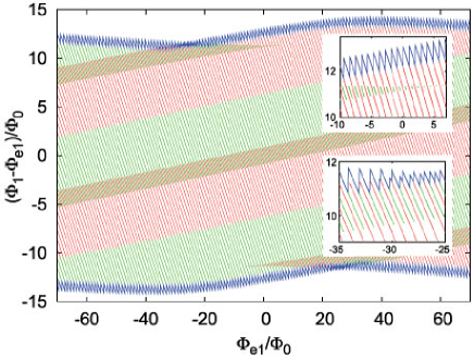
For given external fluxes and , the local minima of the free energy with respect to and are calculated numerically and plotted in Fig. 3. Like for usual rf SQUIDs in the hysteretic regime, the circulating current in the large loop is a multivalued function of external flux if . When the external magnetic field is swept, e.g., in negative direction, the circulating supercurrent follows the lines of local energy minima, as indicated by the red lines in Fig. 3. At the upper end of each line the state becomes unstable and the system switches into the nearest available state with lower free energy, as reflected by the sharp drops in . The envelope of these jumps is periodic, due to a modulation of the maximum by the integrated dc SQUID. This comes from the coupling between and , implying a circulating current also in the small loop (e.g. with ), which contributes to the free energy. Around , states with opposite current in the small junction become stable (see the short green lines in the upper inset in Fig. 3). The stability region for this set of states grows until they eventually become more stable than those with the original (positive) orientation of . This is precisely the region, where these states become involved in the switching process. In this region, states with positive and negative orientation of the current in the small loop alternate, resulting in a doubling of the switching frequency (lower inset in Fig. 3). When the external flux is decreased further, the states with the positive orientation of become energetically unfavorable and their region of stability shrinks, until the switching processes entirely involve states with negative (green lines). In this way, the doubling of the switching frequency is traced back not to a period doubling in the CPR, but to the presence of the two-fold orientation of the current in the -section of the junction.
To compare the numerical results with our experiment we take junction A in the state (tunnel junction, ), junction B in the state (SFS, ), and , , , and . The critical current and inductance of the ring are determined directly from the experimental hysteresis loop in Fig. 2a, while is estimated from previous measurements on similar Nb-PdNi junctions bauer . The dc SQUID inductance and mutual inductance affect mainly size and position of the switching anomaly on the hysteresis loop. For reasonable values of chosen parameters a good agreement is achieved between the experimental data for K and numerical simulations (see Figs. 2 and 4). Note that the ratio of external fluxes differs from the loops area ratio and has (for this sample) negative sign due to the almost orthogonal tilt of the small loop with respect to the sample. Its value determines the number of the observed double switching events and it can be readily determined from the data.
If we assume that the measured reduction of to 75% at K (see Fig. 4) is similar also in , we can well reproduce the observed shift of the switching anomaly towards higher external flux (inner trace in Fig. 4a). The dots in the inset in Fig. 4a show the shift of the switching anomaly vs. the critical current for different temperatures. The solid line denotes the prediction of our theory using the same set of parameters.
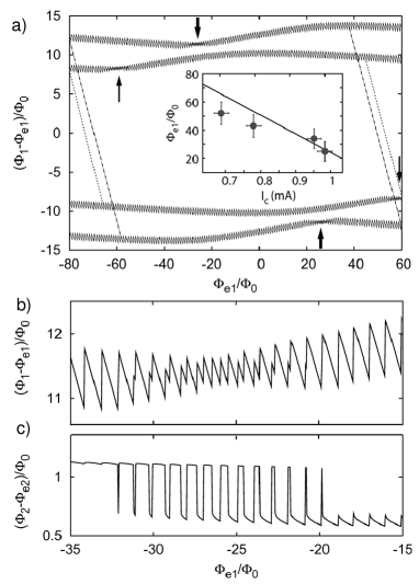
Sequences of the frequency doubling in the flux modulation periodically occur in certain intervals of the external magnetic field, if of the smaller loop is sufficiently large. A zoom onto the substructure is shown in Fig. 4b. Substructures in the switching pattern occur with the period . The corresponding flux modulation in the small loop is shown in Fig. 4c. When the external field is varied, small periodic perturbations induced by the large loop alternate periodically the energies of the two opposite current directions in the small loop, thus forming the bistable region with large flux oscillations. The bistable region is placed symmetrically around the external flux value corresponding approximately to integer number of in the small loop and equal energies for opposite currents in junction B.
Additional calculations show that in the ground state the first substructure occurs in the low external field corresponding to stevan . When both junctions are in the state the first substructure is located at , which corresponds in our case to a very large . However, positions of substructures on the hysteretic loop are strongly shifted from the ground state values, and depend on the mutual inductance. Numerical calculations show that practically the same hysteretic behavior shown in Fig. 4 can be obtained for junctions A and B both in the state with similar parameters of the double SQUID stevan .
To conclude, we studied an rf SQUID containing an inhomogeneous Josephson junction as a weak link. We have found experimentally a doubling of the switching frequency in certain ranges of magnetic flux. The inhomogeneous junction can be modelled as a small dc SQUID with and Josephson junctions. This model explains the observed switching anomaly by a bistable switching of the orientation of the current in the weaker section of the junction. The suggested mechanism is effective, independent of the shape of the CPR in both junctions, and may also be relevant for similar observations in other systems.
We thank M. Reinwald for help with the preparation of the GaAs/AlGaAs-heterostructures. This work has been supported by the German Science Foundation within SFB 689, the Serbian Ministry of Science, Project No. 141014, the Franco-Serbian PAI EGIDE Project No. 11049XG, and US DOE project MA-509-MACA.
References
- (1) A. Golubov, M. Kupriyanov, and E. Il’ichev, Rev. Mod. Phys. 76, 411 (2004).
- (2) C.W. Schneider et al., Europhys. Lett. 68, 86 (2004)
- (3) T. Lindström et al., Phys. Rev. B 74, 014503 (2006).
- (4) J. J. A. Baselmans et al., Phys. Rev. Lett. 89, 207002 (2002).
- (5) Z. Radović, N. Lazarides, and N. Flytzanis, Phys. Rev. B 68, 014501 (2003).
- (6) Z. Radović, L. Dobrosavljević-Grujić, and B. Vujičić, Phys. Rev. B 63, 214512 (2001).
- (7) H. Sellier et al., Phys. Rev. Lett. 92, 257005 (2004).
- (8) S. M. Frolov et al., Phys. Rev. B 74, 020503(R) (2006).
- (9) S. G. den Hartog et al., Phys. Rev. Lett. 77, 4954 (1996).
- (10) P. Dubos et al., J. Vac. Sci. Technol. B 18, 122 (2000).
- (11) T. Kontos et al., Phys. Rev. Lett. 89, 137007 (2002).
- (12) A. Bauer, et al., Phys. Rev. Lett. 92, 217001 (2004).
- (13) A. K. Geim et al., Appl. Phys. Lett. 71, 2379 (1997).
- (14) A. Barone and G. Paterno, Physics and Applications of the Josephson Effect (Wiley, New York, 1982).
- (15) L. D. Landau and E. M. Lifshitz, Course of Theoretical Physics, Vol. 8: Electrodynamics of Continuous Media (Pergamon, Oxford, 1980).
- (16) S. Nadj-Perge and Z. Radović (unpublished).