Generation and Measurement of Non Equilibrium Spin Currents in Two Terminal Systems
Abstract
Generation and measurement of non-equilibrium spin current in two probe configuration is discussed. It argued and shown that spin current can be generated in two terminal non-magnetic system. Further it is shown that these spin currents can be measured via conductance in two probe configuration when the detector probe is ferromagnetic.
pacs:
72.25.Dc, 72.25.Dp, 72.25.MkThe generation, manipulation and detection of spin currents, a flow of angular momentum, is a major goal of spin-based electronics. Thus establishing methods for efficient generation and detection of spin currents is a key for further advancement of spintronics. Amongst the different approaches for spin current generation and manipulation, spin-orbit(SO) coupling is attracting considerable interest. It has been predicted that in a SO coupled system a non zero spin current flows in a direction perpendicular to the applied electric field dyakonov . This gives rise to related spin-Hall effect (SHE) causing spin accumulation at the edges of sample hirsch ; tribhu_prl . The spin accumulation caused by SHE has been detected by optical techniques in a semiconductor channel kato and in two-dimensional electron gas (2DEG) in semiconductor heterostructures wunderlich ; awschalom . Recently electronic detection of spin accumulation in Hall cross geometry which is a four probe system, was reported in Ref.tinkham ; kimura . Till date most of the theoretical and experimental studies are concerned with the observation of SHE which is a spin accumulation caused by the flow of spin current in multi-probe systems. To the best of our knowledge the possibility of spin current generation and detection in two probe systems via conductance measurement has not been reported yet. In this article we address this possibility. We consider two configuration shown in Fig. 1(a) and 1(b) where a 2DEG with SO coupling is sandwiched between two ideal leads without SO coupling. In Fig. 1(a) both leads are non-magnetic while in Fig. 1(b), the detector lead is ferromagnetic(FM) and injector lead is non-magnetic.
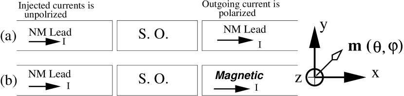
An intuitive understanding of the non-equilibrium spin current generation can be gained by considering the specific case of Rashba SO coupling which in 2DEG has the form, , where and are components of momentum vector in the plane of 2DEG and and are Pauli matrices. Consider the situation when the incident current flows along positive x direction (Fig. 1(a)). In this particular case the Rashba interaction is effectively, because =0. Therfore the outgoing current gets polarized along the y axis. In general SO interaction polarizes scattered beam. This general result is valid for arbitrary form of SO interaction viz. Rashbarashba , Dresselhausdresselhaus or impurity induced SO interaction tribhu_prl ; tribhu_pramana ; tribhu . However the direction and magnitude of polarization for the scattered beam depends on the exact form of SO interactionlandau . Therefore the outgoing charge current in non-magnetic lead two is polarized even though the incident current is unpolarized. Hence it is a true flow of non-equilibrium angular momentum, from SO coupled region to the detector lead.
Let us now focus on the conceptual problem of non-equilibrium spin current measurement via conductance in two probe system with ferromagnetic(FM) detector shown in Fig. 1(b). According to Onsager’s relation the conductance of a two terminal system with one contact being ferromagnetic is invariant upon magnetization reversal, i.e.,G()=G(), where is unit vector along the magnetization direction. In absence of SO interaction, system shown in Fig. 1(b) is rotationally invariant, therefore conductance does not depend on the direction of magnetization and Onsager symmetry is satisfied trivially. In presence of SO interaction since rotation symmetry is broken therefore conductance depends on the absolute direction of magnetization for configuration shown in Fig. 1(b). This is because the detector lead is ferromagnetic (Fig. 1(b)), therefore electrons polarized in the direction of magnetization will transmit easily compared to the electrons polarized along another direction. Hence the conductance of NM/SO/FM system (Fig. 1(b)) will depend on the absolute direction of magnetization and and will be symmetric in and consistent with Onsager symmetry.In other words, G() G(), where and are two arbitrary unit vector along which magnetization is pointing, with the condition that . We show that these conductance variation as a function of absolute direction of magnetization is in phase with the polarization of outgoing current, therefore, it measures the non-equilibrium spin current. Moreover we show that to detect spin currents magnetization reversal is not necessary, rather tilting the magnetization away from the original direction is enough. Magnetization tilting can be achieved using external magnetic fields as is done usuallydieny . The spin currents generated by SO interaction can also tilt the magnetization because it will give rise to a torque on ferromagnetic detector. The torque arises because the spin current generated by SO interaction in general will have components transverse to the magnetization direction of Ferromagnetic contact. The transverse component of spin current is transferred to the FM as torquepareek75 . If the torque is large enough it can tilt the magnetization. For nm scale thick ferromagnetic film it is possible increase the torque by increasing the current densitymyers . In case torque is not large enough to tilt magnetization one can always use an external magnetic filed to rotate the magnetization. Recently Adagideli, Bauer and Halprerin in Ref. bauer have also discussed the possibility of detecting torque related signal via small angle magnetization dynamics in three terminal systems. We stress that our proposal works in two terminal systems and relies on conductance measurements which are easier as well have potential to be used in already developed semiconductor technology.
To study the above discussed effect quantitatively we make use of spin density matrix scattering theory developed in Ref. pareek75 which treats the non-magnetic and magnetic system at the same footing. An incident current in channel ( channel index due to transverse confinement along y direction and is spin index) leads to the following spin density matrix for outgoing currentpareek75 ,
| (1) |
where N is normalization factor ensuring that and and are spin resolved transmission coefficient. The incident current is unpolarized (completely mixed state) therefore, the spin density matrix for the incident current is with =. Here and is the number of up electrons and down electrons respectively. The fact that incident current is unpolarized leads to the following spin density matrix for outgoing current,
| (2) |
From eq.2 and eq.1 it is clear that spin density matrix for outgoing current is completely determined if spin resolved transmission coefficients are known. Since the polarization direction of outgoing current in general will lie along any arbitrary direction, therefore, the transmission coefficient should be calculated in eigen-basis of where is the quantization axis. The polarization along the quantization axis is given by the trace of matrix product of and given in eq.2. However to determine polarization vector we need to calculate polarization components along two more direction which are perpendicular to and are linearly independent. Therefore, for simplicity and clarity we choose two specific cases of quantization axis , namely (a) We fix and vary . In this case three linearly independent axis are , and . (b) We fix and vary . In this case three linearly independent axis are , and . The polarization along a specific axis is calculated using,
| (3) |
where is density matrix given by eq.2.
To obtain results we perform numerical simulation for a two dimensional electron gas (2DEG) using spin dependent recursive Green-function technique. The details of this can be found in Ref. tribhu_pramana ; tribhu . We model the conductor on a square tight binding lattice of size 5050 with lattice spacing a and hopping parameter t. We fix the Fermi energy and take =1 as the unit of energy. The tight binding dimensionless SO parameter is . For disorder we take Anderson model, with on-site energies distributed randomly between [-U/2, U/2], where U is the width of distribution. The results presented are for Rashba Spin-Orbit coupling rashba . However the conclusion remain valid for other type of SO couplings as well.
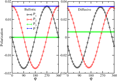
The three linearly independent polarization components of outgoing current are shown in Fig. 2 for non-magnetic configuration shown in Fig. 1(a). We have fixed and rotated the quantization axis in xy plane which correspond to the case (a) discussed above. For ballistic system (Fig. 2,left panel) outgoing currents is perfectly polarized along y axis (curve for has maximum value at =0,and while has maximum and minimum values at and respectively.) This is because current is flowing along positive x axis the effective Rashba interaction becomes as mentioned in the introduction. However in the presence of disorder due to scattering the current direction in 2DEG changes randomly therefore the Rashba coupling retains its two dimensional nature. Hence all three components of polarization are non zero for diffusive system (Fig. 2, right panel). Moreover the magnitude for each component as well the net polarization (shown by straight line with filled circles in Fig. 2) is large in diffusive regime compared to the ballistic case. This is because in presence of disorder electron mobility decrease which in turn increase the effect of Rashba coupling. Therefore moderate disorder will be helpful in generating spin current which is promising from the experimental point since it will not require very clean or ballistic sample.
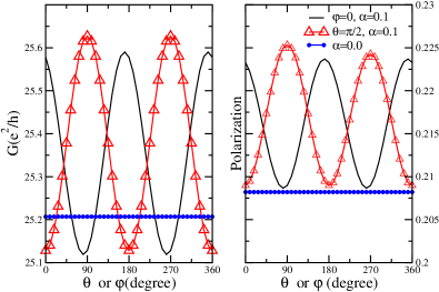
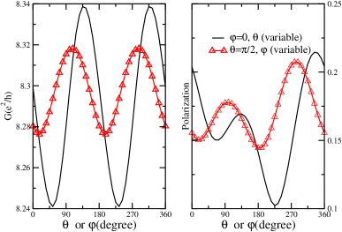
From Fig. 2 it is clear that the outgoing current is spin polarized though the leads are non-magnetic (Fig. 1(a)). Since the leads are non-magnetic therefore the transmission coefficient will be independent of spin polarization of outgoing current and as a consequence conductance will also be independent of quantization axis. Hence with non-magnetic leads one cannot measure the spin current. However, if the detector lead is magnetic (configuration shown in Fig. 1(b)) then transmission coefficient will become spin dependent which will cause conductance to depend on quantization axis as discussed in paragraph 3. This is confirmed in Fig. 3, where we have plotted the conductance(left panel) and polarization (right panel) for the configuration corresponding to Fig. 1(b). Ferromagnet detector is modeled as exchange split with exchange splitting () given as =0.5 tribhu_pramana ; tribhu . The quantization axis is given by the direction of magnetization. We have plotted results for two different quantization axes discussed in paragraph 4 above, namely, (1) =0 and is varied, rotation in xz plane (2) =90 and have been varied, rotation xy plane. We notice that conductance and polarization for zero SO coupling is independent of quantization axis shown by straight line with filled circles in Fig. 3. A finite polarization in absence of SO coupling is due to the presence of ferromagnetic lead. In presence of SO interaction polarization increases compared to the polarization for zero SO coupling which means spin currents is being generated by SO coupling. Moreover polarization and conductance show in phase variation as a function of or . Therefore conductance measures the spin current as discussed before. We notice that, the polarization curve in Fig. 3 for =90 have different values for =90 and =270 which corresponds to y and -y axis respectively. This is because in ballistic system outgoing current is polarized along positive y axis as discussed earlier, therefore, the net polarization decreases (increases) when ferromagnet points anti-parallel (parallel) to y axis. The asymmetry in polarization can be reduced by reducing the magnetization of FM (decreasing ) and by using a weakly coupled detector lead(non-invasive). This would allow one to measure spin currents just due to SO coupling. These finding are robust and survives in presence of disorder as shown in Fig. 4. In presence of disorder due to scattering the outgoing current gets polarized along some arbitrary direction therefore the asymmetry is visible throughout the or range. However the polarization variation still remain in phase with the conductance. We stress that to measure spin current one does not need to reverse the magnetization because the conductance changes as soon as the magnetization is tilted away from the original direction as seen in Figs. 3 and 4.
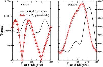
The magnetization can be tilted due to the torque which arises because of spin currents as discussed in paragraph three. Dimensionless torque is defined aspareek75 , where is magnetization vector of FM, is polarization vector of outgoing current and is current. We have plotted the magnitude of torque in Fig. 5 for ballistic (left panel) and diffusive system(right panel) respectively. For ballistic system the torque goes to zero when magnetization is either parallel or antiparallel to y axis (see Fig. 5 left panel, =90 and variable) because outgoing current is polarized along y axis as discussed above and as a consequence torque vanishes. For all other magnetization direction and for diffusive system (Fig. 5, right panel), the torque is always non zero. If the current density is large enough and Ferromagnetic film is of nm scale thick then, magnetization can be tilted just by increasing current and as a consequence one would see a change in conductance which measures the spin current as mentioned earlier.
Finally let us discuss the possibility of observing the spin current related effects presented above. From Figs. 3 and 4 it is seen that conductance changes by 2-3 when magnetization direction is rotated. Magneto-resistance experiments can easily detect changes of this order dieny . The 2-3 conductance change was obtained for dimensionless Rashba SO parameter =0.1. This corresponds to the Rashba spin splitting energy of the order of 10meV. The Rashba SO splitting of 30meV has been reported in Ref.molenkamp1 in II-IV HgTe system. Therefore, the dependence of conductance on absolute direction of magnetization can be easily detected which measures the spin currents. In addition, tunability of Rashba coupling via external gate voltagemolenkamp1 provides further control over the spin current generation, torque and associated conductance change.
In conclusion, we have presented a general method to generate and measure non-equilibrium spin currents in two probe configuration via conductance. We have clarified that magnetization reversal is not required to measure spin currents and shown that it is consistent with Onsager symmetry. Further we have show that torque arising due to spin current can be used to tilt the magnetization which will help in measuring spin currents.
References
- (1) M. I. Dyakonov and V. I. Perel, JETP Lett. 13, 467 (1971);M. I. Dyakonov and V. I. Perel, Phys. Lett. A 35, 459 (1971).
- (2) J. E. Hirsch, Phys. Rev. Lett. 83, 1834 (1999).
- (3) T. P. Pareek, Phys. Rev. Lett. 92, 076601 (2004).
- (4) Y. K. Kato et al., Science 306, 1910 (2004);Y. K. Kato et al., Nature (London) 427, 50 (2004).
- (5) J. Wunderlich, B. Kaestner, J. Sinov and T. Jungwirth, Phys. Rev. Lett. 94, 047204 (2005).
- (6) V. Sih R. C. Myers, Y. K. Kato,W. H. Lao,A. C. Gossard and D. D. Awschalom, Nature Phys. 1, 31 (2005).
- (7) S. O. Valenzuela and M. Tinkham, Nature 442, 176 (2006).
- (8) T. Kimura,Y. Otani,T. Sato,S. Takahashi and S. Maekawa, cond-mat/0609304.
- (9) Yu. A. Bychkov and E. I. Rashba, Sov. Phys. JETP Lett. 39, 78 (1984).
- (10) G. Dresselhaus, Phy. Rev. 100, 580, 1955.
- (11) T. P. Pareek and P. Bruno, Pramana J. Phys. 58, 293 (2002).
- (12) T. P. Pareek and P. Bruno, Phys. Rev. B 63, 165424-1 (2001). T. P. Pareek and P. Bruno, Phys. Rev. B 65, 241305 (2002).
- (13) L. .D. Landau and E. M. Lifshitz Quantum Mechanics 3rd edition pp. 583, Pergamon. E. Merzbacher, Quantum Mechanics 3rd edition pp. 402, Jhon Wiley.
- (14) B. Dieny, J. Magn. Magn Mater. 136, 335(1994).
- (15) T. P. Pareek, Phys. Rev. B 75, 115308(2007).
- (16) E. B. Myers , D. C. Ralph, J. A. Katine, R. N. Louie, and R. A. Buhrman, Science bf 285, 865 (1999).
- (17) I. Adagideli,G. E.W. Bauer and B. I. Halperin, Phys. Rev. Lett. 97, 256601 (2006).
- (18) Y. S. Gui, C. R. Becker,N. Dai, J. Liu,1 Z. J. Qiu, E. G. Novik, M. Schäfer, X. Z. Shu, J. H. Chu, H. Buhmann, and L. W. Molenkamp, Phys. Rev. B 70, 115328 (2004).