Particle Accelerator Conference (PAC 07), Albuquerque, NM, 25-29 June 2007, THPMS082 NFMCC-doc-515
MUON ACCELERATION TO 750 GeV IN THE TEVATRON TUNNEL FOR A 1.5 TeV
COLLIDER††thanks: Supported by DE-FG02-91ER40622 and
DE-AC02-98CH10886.
Abstract
Muon acceleration from 30 to 750 GeV in 72 orbits using two rings in the 1000 m radius Tevatron tunnel is explored. The first ring ramps at 400 Hz and accelerates muons from 30 to 400 GeV in 28 orbits using 14 GV of 1.3 GHz superconducting RF. The ring duplicates the Fermilab 400 GeV main ring FODO lattice, which had a 61 m cell length. Muon survival is 80%. The second ring accelerates muons from 400 to 750 GeV in 44 orbits using 8 GV of 1.3 GHz superconducting RF. The 30 T/m main ring quadrupoles are lengthened 87% to 3.3 m. The four main ring dipoles in each half cell are replaced by three dipoles which ramp at 550 Hz from -1.8 T to +1.8 T interleaved with two 8 T fixed superconducting dipoles. The ramping and superconducting dipoles oppose each other at 400 GeV and act in unison at 750 GeV. Muon survival is 92%. Two mm copper wire, 0.28 mm grain oriented silicon steel laminations, and a low duty cycle mitigate eddy current losses. Low emittance muon bunches allow small aperatures and permit magnets to ramp with a few thousand volts. Little civil construction is required. The tunnel exists.
1 MUON COLLIDER INTRODUCTION
A muon collider [1] can do s-channel scans to try to split the Higgs doublet [2]. At a 1.5 TeV frontier energy, there may be a large array of supersymmetric particles and, if large extra dimensions exist, mini black holes [3]. Like SPEAR, the resolution of a muon collider is unaffected by beamstrahlung. Muon ionization cooling is the key to this machine and a vigorous R&D program is underway [4, 5]. Given a large initial emittance, focusing magnets and RF cavities must be in close proximity. Magnetic fields perpendicular to RF cavity surfaces enhance breakdown [6]. Possible cures include lattices with magnetic fields parallel to RF cavity surfaces to bend electrons back into the cavity surface before they can accelerate, high pressure hydrogen gas in RF cavities to slow electrons [7], grooved RF cavity walls to trap electrons [8], or high melting point, low density materials such as beryllium to allow sparks to spread their energy without melting RF cavity walls. 6D cooling guggenheims [9] and rings [10] show promise. Final muon cooling requires short focal length lattices. High Tc superconductors at 4K can carry large currents in the 35 to 50 T range [11]. Parametric resonances [12] and inverse cyclotrons [13] are also being explored for cooling.
2 30 TO 400 GeV, 400 Hz RING
Historically synchrotrons have provided economical acceleration. Here we outline a relatively fast 400 Hz synchrotron [14] for muons, which live for 2.2 S. A 200 S (1250 Hz) pulsed wiggler has been built with vanadium permendur which is similar to the magnets required here. It achieved 2.1 T in a 4 mm gap with a 10 cm wavelength [15]. In eq. 1, the dipole vertical aperture, , is calculated using an emittance of 25 mm-mrad [5] and the Fermilab main ring FODO lattice parameter, 99 m. Acceleration to 30 GeV might use dogbone recirculating LINACs and Fixed Field, Alternating Gradient (FFAG) rings [16].
| (1) |
Eqs. 2 and 3 are now used to calculate the dipole voltages and amperages in Table 1. is the number of turns in a coil. A simple LC circuit with an IGBT or SCR switch is used. The voltages are reasonable because the magnetic field volume is small and little energy is stored in the grain oriented 3% silicon steel (Table 2). Achieving good field quality in small aperture magnets needs to be explored.
| (2) |
| (3) |
| Injection energy | GeV | 30 | 400 | 400 |
| Extraction energy | GeV | 400 | 750 | 750 |
| Dipoles / half cell | 4 | 2 | 1 | |
| Dipole length, | m | 6.3 | 3.75 | 7.5 |
| Bore height, | mm | 6 | 5 | 5 |
| Bore width, | mm | 30 | 50 | 50 |
| Initial magnetic field, | T | 0.14 | -1.8 | -1.8 |
| Final magnetic field, | T | 1.8 | 1.8 | 1.8 |
| Orbits | 28 | 44 | 44 | |
| Acceleration period | ms | 0.59 | 0.92 | 0.92 |
| Frequency, | Hz | 400 | 550 | 550 |
| Coil turns, | 4 | 4 | 2 | |
| Coil resistance, | 4500 | 2700 | 1350 | |
| Current, | A | 2200 | 1800 | 3600 |
| Magnet energy, | J | 1500 | 1200 | 2400 |
| Magnet inductance, | H | 630 | 760 | 380 |
| Capacitance, | F | 250 | 110 | 220 |
| Voltage, | V | 3400 | 4700 | 4700 |
| Power Consumption | kW | 0.6 | 1.4 | 2.8 |
Using eq. 4, the skin depth, , of steel with at 400 Hz is 0.3 mm. From eq. 5, only 2% of 0.28 mm thick steel is lost due to shielding by eddy currents [17]. The skin depth for 18 n-m copper at 400 Hz is 3.4 mm.
| (4) |
| (5) |
Now we estimate the power consumption of the magnets. Laminations are laid out to minimize core losses (Fig. 1). Eq. 6 [18] gives a value of 23 W/kg for the steel. An average magnetic field of 1.6 T is used. Both eddy currents and hysteresis losses, , which scale with the coercive force, Hc, given in Table 2, are included. Eddy currents alone [19] give 15 W/kg in eq. 7. The total core loss for a one ton dipole is 23 kW. losses for four turns of cm copper (4500 ) carrying 2200 A of sinusoidal current are 11 kW. Using eq. 7 with an 0.1 T field and coils made of 2 mm transposed strands, the eddy current losses in the copper are 6 kW. So multiplying 40 kW per dipole times 800 dipoles and adding 6% for quadrupoles, one gets 34000 kW. But the magnets are only on for half of a 400 Hz cycle, 13 times per second, for a duty cycle of 1.6% and a total power consumption of 540 kW. A choke and diode are used to do a leisurely reset of the polypropylene capacitor bank polarity for each new cycle.
| (6) |
| (7) |
| Steel | -m) | Hc(A/m) | 1.0 T | 1.5 T | 1.8 T |
|---|---|---|---|---|---|
| .0025% Carbon | 100 | 80 | 4400 | 1700 | 240 |
| Oriented () Si | 470 | 8 | 40000 | 30000 | 3000 |
| Oriented () Si | 470 | 4000 | 1000 |

3 400 TO 750 GeV, 550 Hz HYBRID RING
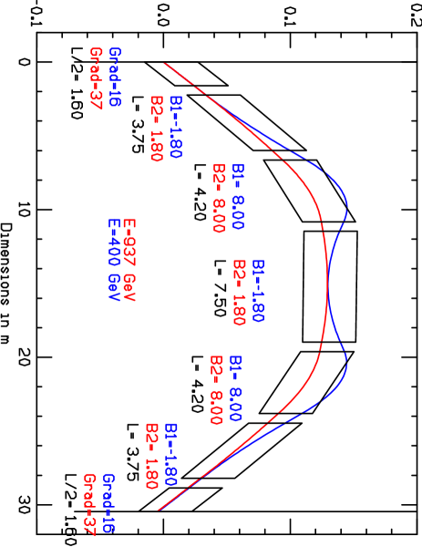
The 400 GeV Fermilab main ring FODO lattice is slightly modified to reach 750 GeV. The 30 T/m quadrupoles are lengthened from 1.7 m to 3.2 m and run at 150 Hz. The four ramping dipoles per half cell are replaced by five dipoles, two fixed 8 T superconducting dipoles in between three dipoles ramping from -1.8 T to 1.8 T at 550 Hz, as shown in Fig. 2. The ramping dipoles oppose the superconducting dipoles at injection and work in unison at extraction. Ramping dipole parameters are given in the last two columns of Table 1.
Now we estimate the power consumption of the magnets. Using an average magnetic field of 1.6 T and a frequency of 550 Hz, Eq. 6 [18] gives a value of 40 W/kg for the 0.28 mm grain oriented 3% silicon steel. The total core loss for a 2400 kg, 7.5 m long dipole is 96 kW. losses for two turns of cm copper (1350 ) carrying 3600 A of sinusoidal current is 9 kW for the 7.5 m long dipole. Using eq. 7 with an 0.1 T field and coils made of 2 mm transposed strands, the eddy current losses in the copper are 13 kW. So multiplying 118 kW per 7.5 m dipole times 200 7.5 m and 400 3.75 m dipoles and adding 6% for quadrupoles, one gets 50000 kW. But the magnets are only on for a 550 Hz cycle, 13 times per second, for a duty cycle of 2.4% and a total power consumption of 1200 kW.
4 1.3 GHz, 10 MW KLYSTRONS
Acceleration from 30 to 400 GeV uses 14 GV of 1.3 GHz superconducting RF in 42 locations evenly spaced around the ring. The acceleration occupies 0.59 ms and 28 orbits. Muon survival is 80%. Forty-two 10 MW klystrons allow the energy extracted by a pair of muon bunches to be replaced. One RF coupler for every three cells is required.
Acceleration from 400 to 750 GeV uses 8 GV of 1.3 GHz superconducting RF in 12 locations evenly spaced around the ring. The acceleration occupies 0.92 ms and 44 orbits. Muon survival is 92%. Twenty-four 10 MW klystrons allow the energy taken by a pair of muon bunches to be replaced. One RF coupler for every three cells is required.
Running at 13 Hz, the cryogenics and klystron modulators require 4 and 22 MW of AC wall power, respectively.
A bunch with muons extracts 8% of the energy from an RF cavity leading to head/tail, wakefield [22], and HOM [23] issues. One cell stores 13 joules at 31.5 MV/m. However, as shown in eqs. 8 and 9, there are synchrotron oscillations [24] to aid longitudinal dynamics. is the harmonic number (number of 0.23 m RF wavelengths around the ring). The transition is 18 for the main ring, which gives a momentum compaction, , of .
| (8) |
| (9) |
Muon bunches must stay in phase with the RF. The muon speed increase from 0.99999380 to 0.99999996 in the first ring can be corrected by increasing the orbital radius by 6 mm during acceleration. The one in 40000 path length decrease in the second ring can be corrected by increasing the orbital radius by 25 mm during acceleration.
A longitudinal emittance of 0.072 m-rad [5] leads to an 0.01 m long muon bunch injected at 30 GeV/c with a 2.5% momentum spread, i.e. , where . Better might be 0.005 m and 2% [22]. The RF wavelength is 0.23 m. A muon on crest gets 4% more acceleration than one 0.01 m (150) off crest.
Using eq. 10, and integrating over the acceleration cycle from 30 to 750 GeV with muons at 13 Hz, and neglecting downtime and straight sections in the ring, a person would receive a dose of a millirem at 2700 m from decays into neutrinos, if they stood in the beam constantly. This is 1% of the federal limit, 10% of the Fermilab offsite limit, and equivalent to eating two bananas a week. Note that the Fox River is 5000 m away from and 4 m below the Tevatron, so neutrinos at 2700 m are still underground.
| (10) |
Many thanks to A. Garren, D. Trbojevic, K. Bourkland, D. Wolff, R. Rimmer, D. Li, H. Padamsee, M. Syphers, S. Kahn, and D. Neuffer for sage advice.
References
-
[1]
M. M. Alsharo’a et al., Phys. Rev. ST Accel. Beams 6 (2003) 081001;
C. M. Ankenbrandt et al., Phys. Rev. ST Accel. Beams 2 (1999) 081001;
D. Ayres et. al., physics/9911009;
R. Raja and A. Tollestrup, Phys. Rev. D58 (1998) 013005;
R. B. Palmer et al.,
physics/9610009;
NATO Adv. Study Inst. Ser. B Phys. 365 (1997) 183;
Nucl. Phys. Proc. Suppl. 51A (1996) 61;
AIP Conf. Proc. 372 (1996) 3;
G. Penn and J. S. Wurtele, Phys. Rev. Lett. 85 (2000) 764; M. A. Green et al., IEEE Trans. Appl. Supercond. 9 (1999) 1049; K. Hirata et al., AIP Conf. Proc. 372 (1995) 330;
W. W. M. Allison et al., J. Phys. G34 (2007) 679; A. Skrinsky and V. Parkhonchuk, Sov. J. Part. Nucl. 12 (1981) 223; A. N. Skrinsky, AIP Conf. Proc. 352 (1996) 6 and 7;
G. I. Budker, AIP Conf. Proc. 352 (1996) 4 and 5;
D. V. Neuffer, Nucl. Instrum. Meth. A350 (1994) 27;
AIP Conf. Proc. 156 (1987) 201; Part. Accel. 14 (1983) 75. - [2] V. Barger et al., Phys. Rept. 287 (1997) 1.
- [3] R. Godang et al., Int. J. Mod. Phys. A20 (2005) 3409; M. Cavaglià et al., hep-ph/0609001; AIP Conf. Proc. 805 (2006) 338; Phys. Lett. B507 (2003) 7; JHEP 0706 (2007) 055.
- [4] Y. Torun, Nucl. Phys. Proc. Suppl. 155 (2006) 381.
- [5] R. B. Palmer et al., PAC 07, Albuquerque (25-29 Jun 2007).
- [6] J. Norem et al., Phys. Rev. ST Accel. Beams 6 (2003) 072001; Phys. Rev. ST Accel. Beams 8 (2005) 072001.
- [7] K. Yonehara et al., Nucl. Phys. Proc.Suppl. 149 (2005) 286.
- [8] L. Wang et al., Nucl. Instrum, Meth. A571 (2007) 588.
- [9] A. Klier, Low Emittance Muon Collider Workshop, Fermilab (6-10 Feb 2006), http://www.muonsinc.com/mcwfeb06.
- [10] R. Palmer et al., Phys. Rev. ST Accel. Beams 8 (2005) 061003; R. Fernow, ‘ICOOL,’ eConf C990329, THP31.
- [11] S. Kahn et al., EPAC 06, eConf C060626, WEPLS108; H. Miao et al., IEEE Trans. Appl. Supercond. 15 (2005) 2554; D. J. Summers, NuFACT 06, Irvine, CA (24-30 Aug 2006).
- [12] S. A. Bogacz et al. Nucl. Phys. Proc. Suppl. 155 (2006) 275.
-
[13]
D. J. Summers et al., AIP Conf. Proc. 821 (2006) 432;
Int. J. Mod. Phys. A20 (2005) 3851. - [14] D. J. Summers et al., AIP Conf. Proc. 721 (2004) 463; PAC 03, hep-ex/0305070; J. Phys. G29 (2003) 1727; Snomass 01, hep-ex/0208010; Snowmass 96, physics/0108001; SESAPS, Bull. Am. Phys. Soc. 39 (1994) 1818.
- [15] J. Gallardo et al., IEEE Trans. Magnetics 30 (1994) 2539.
-
[16]
J.S.Berg et al., Phys.Rev.ST Accel.Beams 9 (2006) 011001; S.A. Bogacz,
Nucl. Phys. Proc. Suppl. 149 (2005) 309;
C. H. Albright et al., physics/0411123. - [17] K. L. Scott, Proc. IRE 18 (1930) 1750.
- [18] W. McLyman, ‘Magnetic Core Selection for Transformers and Inductors,’ ISBN 0-8247-1873-9 (1982).
- [19] H. Sasaki, ‘Magnets for Fast- Cycling Synchrotrons,’ Conf. Synch. Radiation, Indore, India (3- 6 Feb 1992) KEK 91-216.
- [20] R.M. Bozorth, ‘Ferromagnetism’ (Van Nostrand 1951) 90.
- [21] F. Bertinelli et al., IEEE Trans. Appl. Supercond. 16 (2006) 1777.
- [22] D. V. Neuffer, Nucl. Instrum. Meth. A384 (1997) 263.
- [23] H. Padamsee, 9th Workshop on RF Superconductivity, Santa Fe, NM (1–5 Nov 1999) eConf C9911011, 587.
- [24] E. D. Courant and H. S. Snyder, Annals Phys. 3 (1958) 1.