Analysis of a four-mirror cavity enhanced Michelson interferometer
Abstract
We investigate the shot noise limited sensitivity of a four-mirror cavity enhanced Michelson interferometer. The intention of this interferometer topology is the reduction of thermal lensing and the impact of the interferometers contrast although transmissive optics are used with high circulating powers. The analytical expressions describing the light fields and the frequency response are derived. Although the parameter space has 11 dimensions, a detailed analysis of the resonance feature gives boundary conditions allowing systematic parameter studies.
pacs:
07.60.Ly, 95.55.Ym, 42.25.HzI Introduction
To improve the strain sensitivity of interferometric gravitational wave detectors advanced interferometer topologies such as Resonant Sideband Extraction (RSE)Mizuno et al. (1993) and Signal RecyclingMeers (1988) will be realized in the next generation. The sensitivity in the shot noise limited region will be increased by a factor of about 10 over the current detectors by increasing the circulating laser power. Using the Power Recycling technique together with high finesse arm cavities in each interferometer arm and high power lasers, the circulating light power will almost reach the Megawatt regime. But the performance and sensitivity of these topologies strongly depends on the interferometers contrast. Thus, we investigated a topology- the four-mirror cavity enhanced Michelson- with the potential to minimize the influence of imperfections in the contrast and in addition the effect of thermal lensing although transmissive optics are used with high circulating powers.
In this paper the investigation of the four-mirror cavity with respect to the shot noise limited sensitivity is presented. In Section II the analytic expressions for the carrier fields and the frequency response of the four-mirror cavity will be derived. The expressions will be given in analogy to a two-mirror cavity (Fabry-Perot-Resonator) offering an intuitive understanding of the whole coupled system. Because of the huge parameter range, configurations yielding satisfactory sensitivities are not obvious. Thus, to analyze the four-mirror cavity systematically some basic assumptions and boundary conditions are necessary. In Section III such boundary conditions will be derived from a detailed analysis and visualization of the resonance feature. This analysis reduces the number of free parameters from 11 to 6. Furthermore, it will be shown that the parameters for the second cavity can be chosen to give peak sensitivities at selectable frequencies. These parameters serve as a starting point for all other parameters which drastically reduces the number of steps in numerical parameter studies. In Section IV the dependence on the free parameters is demonstrated for special cases and exemplary shot noise limited sensitivities and properties of the four-mirror cavity are shown in comparison to Advanced LIGOWeinstein (2002).
The intention of the future interferometric gravitational wave detectors is the enhancement of the shot noise limited sensitivity by increasing the circulating light powers inside the interferometer. Here, the available laser input field would be ideally exploited if no power is reflected to the interferometers input. This can be realized using impedance matched Fabry-Perot resonators (cavities) in each interferometer arm. Using high finesse resonators would also provide desirable high circulating powers. But the bandwidths of these resonators are very small leading to an unsatisfactory sensitivity in the detection band beyond the arm resonators’ bandwidth. To broaden the bandwidth for signal sidebands the RSE schemeMizuno et al. (1993) was proposed. Here, an additional mirror is placed in the interferometer output forming together with the arm cavities’ coupling mirrors the extraction cavity. Since this cavity includes the beam splitter, the performance of the sideband extraction strongly depends on the interferometers contrast. If the intra cavity losses (mainly caused by a bad interferometer contrast) become comparable to the transmission of the arm cavities’ coupling mirrors, the sideband extraction collapses. To overcome this problem, the power recycling techniqueDrever et al. (1983) is used. This technique allows the increasing of the coupling mirrors transmission so that the intra cavity losses in the extraction cavity become less significant. To maintain the effective power build up in the arm cavities, the wasted power (now reflected from the overcoupled arm cavities) is recycled in the power recycling cavity (also including the beam splitter) in such a way, that the complete optical configuration is still impedance matched. However, the power recycling leads to relative high optical powers in the recycling cavity. Here the amount of allowable power is limited by the nonzero absorption of the used transmissive optics and their coatings. Due to the effects of thermal lensingWinkler et al. (1991); Strain et al. (1991) and thermal expansion of the optics surfaces the heating by optical absorption causes phase front distortions leading to poor interference quality (critical for the RSE-scheme) at the dark port operating point. This causes higher optical power on the photo detector and therefore higher shot noise. Furthermore, the thermal lensing in the substrates of the arm cavities’ coupling mirrors leads to an unstable cavity for the RF-modulation sidebands needed for controlling the interferometersMcClelland et al. (1999).
The strong dependence on the contrast and the effect of thermal lensing in these advanced interferometers were the motivation for investigating techniques and alternative interferometer topologies to solve these problems. The use of alternative substrate materials, for example sapphire, is one solution Tomaru et al. (2002). Active thermal compensation provides a further opportunity to reduce thermally induced phase front distortionsLück et al. (2000); Lawrence et al. (2002, 2004); Degallaix et al. (2004). Basically different and promising is the use of all-reflective interferometer topologiesDrever (1995). At present the application of gratings in future detector topologies and implementation issues are investigatedBunkowski et al. (2004, 2005). However, the fabrication of appropriate reflection gratings with the dimensions and quality needed for the application in interferometric gravitational wave detectors still poses a problem.
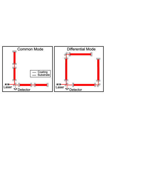
We investigated a topology using additional mirrors in each interferometer arm and not in the input and output. If an additional mirror is placed in each interferometer arm the power build up and the extraction of signal sidebands could be performed without including the beam splitter in a cavity. Thus, the losses at the beam splitter would not limit the performance of the interferometer. But with a three-mirror cavity the effect of thermal lensing could not be avoided because at least one optical substrate is embedded in a resonator with high circulating power. Also, the resonance condition of carrier and sidebands would not be decoupled. Thus, with a three-mirror arm cavity there would be no way to tune the resonators for carrier and sidebands independently. But if a fourth mirror is placed in the arms, a second long resonator is formed (Figure 1). This configuration yields resonance states where the circulating light power in the second cavity embedding the optical substrates is small compared to those of the first and third resonators. In this configuration, the resonance conditions of carrier and sidebands are also coupled. However, the coupling between the first and third resonator can be varied with the effective transmission of the second resonator. Thus, the frequencies of the corresponding resonance doublet of these coupled resonators are tunable. In fact the four-mirror cavity has a resonance triplet. But the length of the second resonator is chosen to be small (see Section III) leading to a high resonance frequency with no effect in the frequency range of interest.
II Analytical description
II.1 Carrier fields
Since the reason for increasing the circulating light power in advanced topologies is the improvement of the sensitivity in the shot noise limited frequency region, initially the impact of radiation pressure noise is not considered. Moreover, taking radiation pressure noise into account would expand the parameter range as the masses of the mirrors and the input power also influence the frequency response. Thus, it is suitable to select parameter configurations at first with respect to satisfying shot noise limited sensitivities. After that the selected configurations can be tested for the effect of radiation pressure.
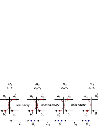
If the mirrors are assumed to be ideal (loss free) the carrier fields in the four-mirror cavity can be calculated in analogy to a two-mirror cavity. The enhancement of the input fields inside the corresponding cavities is given by (the notation refers to Figure 2)
| (1a) | |||||
| (1b) | |||||
| (1c) | |||||
For a detailed derivation of the expression for a two-mirror cavity refer for example toHeinzel (1999). In Equation (1b) and (1c) the abbreviations and are used to maintain the appearance of a simple two-mirror cavity. They stand for the reflection of the third cavity (behaving like an ordinary two-mirror cavity) (M34) given by
| (2) |
and the reflection of the three-mirror cavity containing M2, M3 and M4 (labeled M234 in the following) given by
| (3) |
Note that these complex expressions are frequency dependent values. Furthermore, the input field of the third resonator is and that of the second one is . However, writing similar to the two-mirror cavity case and thinking of M34 and M234 as compound mirrors offers an easier understanding of these expressions.
II.2 Signal sidebands
The basics of the response to gravitational waves are described for example inMizuno et al. (1997) for a Michelson interferometer with ordinary two-mirror arm cavities. In this section we transfer these results to the four-mirror cavity case.
The normalized transfer function to the detection port for signal sidebands generated in the four-mirror cavity by gravitational waves (called ‘GW-transfer function’ in the following) is composed of three parts corresponding to the three resonators formed by the four-mirror cavity. Each of the three parts is the sum of the transfer function for the upper sidebands () and the lower sidebands ().
One obtains
| (4) |
for the readout of the phase modulation and
| (5) |
for the readout of the amplitude modulation. For an arbitrary operating point the terms have the form
| (6) |
Since sidebands generated by a traversing gravitational wave are impressed due to a modulation process their amplitudes are proportional to the carrier field. Accordingly the expression for the corresponding carrier field (first term of Equation (6)) is contained in . Note that here the input field is assumed to be unity because represents a normalized transfer function.
The expression describing the transfer from a gravitational wave to phase shift (modulation depth) is given byMizuno et al. (1997)
| (7) |
where is the optical path length. Each sideband impressed on the carrier by this weak phase modulation has the amplitude . To obtain the magnitude of the sidebands generated per round trip in the respective cavity (second term in Eq. (6)), the amplitude attenuation (per round trip) of this cavity needs to be taken into account. In the case of the first and second cavity the reflecting mirror M and thus the attenuation is frequency dependent. Accordingly, the first half and the second half round trip needs to be considered independently. One obtains
| (8) |
where is the reflection of the respective reflecting mirror M (i.e. in the case of the first cavity is ). The first term in the parentheses describes the attenuation of the sidebands generated on the first half round trip. These sidebands are reflected at M234 with . The phase accounts for the delay incurring on the second half round trip. The second term in the parentheses describes the sidebands generated on the second half round trip. The amplitude of these sidebands is proportional to the reflected carrier field. Thus in this case the attenuation is that of the carrier amplitude. Here the phase factor describes the carriers phase delay incurred on the first half round trip.
In addition the phase relation between the signal sidebands induced in different cavities needs to be included. Thus, the geometric layout of the resonators (refer to Figure 1) needs to be taken into account as well. If the four-mirror cavity is not folded, signal sidebands of gravitational waves are impressed in common mode. But if for example the first and third resonator are orientated orthogonally to each other, the corresponding sidebands are impressed differentially (due to the quadrupole nature of gravitational waves). Thus, in the differential mode and have different signs.
Whereas the first two terms of Eq. (6) principally describe the sideband generation in the respective cavities, the frequency response is mainly determined by the third term in Eq. (6). The frequency dependent enhancement of the sidebands inside the cavities and the transfer out of the cavities to the detection port can be obtained from by substituting
| (9) |
where describes the phase delay incurring while propagating over the length . This becomes clear considering for example the first cavity. The expression describes the enhancement of the amplitude injected at M1 into the first cavity (refer to Figure 2). The signal sidebands are generated inside the cavities, get resonantly enhanced, and are then transmitted through M1 to the detection port. Hence we do not need to multiply the sideband amplitudes by upon injection but during the extraction (transmission through M1) of the cavity and Eqs. (1a)-(1c) are valid not only for the externally injected carrier but also for the internally generated sidebands.
The shot noise limited sensitivity is given by the noise to signal ratio of the signal and the phase fluctuation equivalent to shot noiseWinkler (1991)
| (10) |
leading to
| (11) |
where is the power of the incident carrier light. Note, that is calculated for a single interferometer arm. This results in an additional factor of 1/2 for the sensitivity of the whole interferometerMizuno (1995). Since this sensitivity depends on eleven parameters (3 macroscopic lengths, 3 tunings, 4 reflectivities and the geometric layout), a qualitative and intuitive understanding of the resonance feature is necessary to find some basic assumptions and boundary conditions which allow a systematic analysis of the configuration.
III Reduction of parameter range
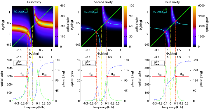
The lower graphs show the frequency response of the optical gains (green curves) and the phasing (blue curves) along the green line () in the upper graphs. The frequency scale is calculated as . Thus, is related to the symmetry point. The frequency splitting is defined with respect to this symmetry point. The connections to the upper graphs demonstrates that the responses of the first and third resonator are symmetric (yellow line) and furthermore that resonances in the frequency response can be pre-estimated by the intersection of with the loci of resonance.
III.1 Basic assumptions
Since the four-mirror cavity is meant as an alternative to RSE-topologies, we will derive some basic boundary conditions for the comparison with the Advanced LIGO optical configurationWeinstein (2002). In consequence, the maximum interferometer arm length is set to 4 km. The calculated strain sensitivities are related to an input power of 125 W. The transmission of the end mirror M4 is set to 50 ppm. In addition, to avoid thermal effects in the optical substrates embedded in the second cavity, the power in this cavity needs to be relatively small. Thus, signal sidebands induced in this cavity are small compared to those induced in the first and third one. Accordingly, the length does not need to be long to enhance the sensitivity for gravitational waves. It can be shown that even the shape of the GW-transfer functions is not significantly affected by . Thus, is arbitrarily set to 10 m for all calculations. Hence the second cavity can be understood as an etalon whose transmission determines the coupling of the first and third cavity and thus the frequency splitting of the corresponding resonance doublet. This is one key feature of the topology. The four-mirror cavity behaves like a three-mirror cavity with variable coupling. The properties of the second cavity solely determine the frequency splitting.
III.2 Resonance feature
The transmission of an ordinary two-mirror cavity becomes maximum on resonance. In analogy to this, the resonance condition of the four-mirror cavity corresponds to local maxima in the transmitted field. Concerning a two-mirror cavity, the incident light resonates if the phase shift per round trip equals 0 mod(2). Here the phase shift comes from the phase delay incurred while traveling twice the macroscopic length . In the case of the four-mirror cavity, the phasing in the first cavity is composed of the corresponding delay and the phase shift in reflection of M234. For given reflectivities and tunings and , the first cavity can be understood as a two-mirror cavity with M234 as the end mirror giving an additional phase shift. Thus the resonance condition (leading to a maximum light field) in the first cavity can be determined according to
| (12) |
(shown by the cyan line in the upper graphs of Figure 3). Since the enhancements of the second cavity () and the third cavity () are constant if and are fixed (refer to Eqs. (1a) and (1b)), a maximum light field in the first cavity leads to maximum light fields in the second and third cavity. This relation drastically reduces the parameter range for the resonances of the four-mirror cavity.
III.3 Power in substrates
Another boundary condition can be derived from the point symmetry in the loci of maximum optical gain. Concerning the pattern of the internal fields in the --plane, those of the first and third resonator are point symmetric whereas that of the second one is not (refer to Figure 3). Considering the absolute values of the carrier fields (Eqs. (1a)-(1c)) reveals that the carrier fields are point symmetric in the tunings . Due to the fact that all tunings in appear with the factor the relation
| (13) |
is valid explaining a point symmetry around the origin . Since in general is not zero but tuned () to give a certain frequency splitting, the relation of Eq. (13) is not fulfilled. In this case
| (14) |
showing that is not point symmetric in the --plane. The symmetry still existent in the pattern of and comes from the point symmetric phase shift in reflection around the resonance in M234. Here M234 is considered as a two-mirror cavity with M23 as the coupling mirror. Accordingly the phase shift in reflection of M234 must correspond to the point symmetric two-mirror cavity case. From this phase shift the coordinates of the symmetry point can be determined in analogy to Eq. (12) as
| (15) | |||||
| (16) |
Note, that in Eq. (15) is determined in reflection of the second cavity (etalon). This is possible because of the reciprocity concerning the resonance in M234. Here reciprocity means that the transmission and thus the resonance condition of M234 must not differ if the light is injected at M4 instead of M2.
Then, to fulfill the condition of low power in the second resonator, only those operating points lying on the lower left resonance branch are suitable (refer to the optical gain of the second cavity shown in the middle of Figure 3). Since the pattern of the internal carrier fields are only determined by the reflectivities of the mirrors, appropriate operating points with respect to the power buildup can be investigated independently from the macroscopic cavity lengths . The choice of the lengths concerns only the GW-transfer function.
III.4 Frequency response
The frequency response of the four-mirror cavity is represented by a cut through the --plane (upper graphs in Figure 3) along an oblique line given by
| (17) |
where and corresponds to the operating point of the carrier light. The slope of this line is determined by the ratio because the tunings change with the frequency according to . Thus, resonances in the transfer function are indicated by the intersections of with the loci of maximum optical gain given by Eq. (12). The frequency splitting is given by the coordinates of these intersection points and is counted from the symmetry point (refer to the lower graphs of Figure 3). The loci of maximum optical gain are determined in dependence of given (and ). Thus, they are related to maxima along cuts parallel to the -axis. Accordingly these maxima are not necessarily local maxima along the line . However, it is useful to pre-estimate resonances in the transfer functions considering these intersections (see below). As the transmission of the second cavity determines the coupling between the first and third resonator and thus the frequency splitting an expression can be derived giving as a function of this frequency splitting. For this purpose we consider a three-mirror cavity with equal length and and an end mirror with . Here the transmission (also ) of the second mirror determines the frequency splitting. Solving the intersection for gives
| (18) |
Note that the resonance frequencies of the single resonators depend on their macroscopic lengths according to . Thus, the frequency splitting of the coupled resonators is related to the lengths and , too. In the following explicit values of always refer to and to the symmetry point. For fixed reflectivities and the tuning leading to the desired is given by
| (19) |
Since the effective transmission of the second cavity is the decisive parameter for the frequency splitting, and initially can be chosen almost arbitrarily. Only the coordinates of the symmetry point depend on and . The pattern of and related to this symmetry point stay the same. Later the optimal values are determinable by the boundary condition of low power in the second cavity. Accordingly, for a certain the enhancement of the carrier light only depends on , and ( is 50 ppm). The GW-transfer function additionally depends on and . Thus, the parameter space for the sensitivity of the investigated topology is reduced to a six dimensional one. Additionally, can be chosen from Eq. (19) to give a certain frequency splitting. Then, the symmetry point from Eqs. (15) and (16) serves as starting point for and leading to a reduction of the parameter range for the tunings.
IV Parameter studies
IV.1 Special cases
The analysis of the resonance feature in Section III revealed that the resonance of the carrier light does not depend on the macroscopic lengths , because the resonance is determined by the microscopic lengths (tunings). Furthermore, it was stated that the sensitivity for gravitational waves is proportional to the carrier amplitudes in the cavities. Thus, operating points yielding satisfying sensitivities are restricted to states where the carrier is on resonance (or close to resonance). For given reflectivities these states are determined by Eq. (12). First we investigate the power buildup (optical gain) in the first and third cavity in dependence of the frequency splitting induced by the tuning of the second cavity. Here, the reflectivities and were set to 0.999 each and was set to 0.993. The frequency splitting was investigated in a range from 50 Hz to 1 kHz corresponding to the detection band of terrestrial gravitational-wave detectors. Furthermore, the respective operating points were chosen as the intersection point (located on the lower left resonance branch) of with the loci of maximum optical gain. Note, that the carrier is resonant on these states (refer to Figure 3). Then the upper sidebands are expected to be resonant at frequencies . The corresponding tuning was determined by Equations (18) and (19). The cavity lengths and were set to 2 km each. This investigation revealed that both the optical gain and the resonances’ bandwidth in these special states are independent of the frequency splitting in the investigated region. Figure 4 shows the shot noise limited sensitivities for various tunings .
Since for these states the tunings and the cavity lengths were determined with respect to certain frequency splittings and resonances in the frequency response, is the only remaining free parameter affecting the optical gains. Accordingly, these states are investigated for the dependence on . The results are shown in Figure 5. It can be seen that the accuracy of the estimation of resonances in the response depends on . This is because on the one hand the intersection points indicating these resonances correspond to local maxima along and not along . On the other hand these intersection points were determined independent of . Considering an extreme case clarifies that the resonances in the frequency response change with . If is assumed, the influence of the first cavity is negligible. In this case, the resonance feature is dominated by M234 whose resonance corresponds to the symmetry point. Accordingly, for a low the frequency response becomes maximum on the symmetry point explaining the peak sensitivity around 50 Hz for (solid curve in Figure 5). Furthermore it can be seen, that the impedance matched case optimally exploiting the laser input field yields a better sensitivity compared to Advanced LIGO only in a very narrow region.
Figure 6 shows the sensitivity for different ratios . This ratio determines the slope of the oblique line in Figure 3 representing the frequency response. Accordingly, the intersection points of this line with the loci of resonance vary with this ratio. Also the magnitude of the signal sidebands induced in a cavity scale with its length (refer to Eq. 7)). Hence if is greater than the GW-transfer function is dominated by the sidebands induced in the first cavity (if the powers in the first and third cavity are similar).
The optical gain is very low around the symmetry point as it can be seen in Figure 3. This low optical gain corresponds to the bad sensitivity around 50 Hz for (solid curve in Figure 6). This fact indicates, that satisfying sensitivities in a broad frequency range are only achievable for configurations with . Also configurations with very short (or ) yield no satisfying sensitivities. In these cases, the four-mirror cavity behaves like an ordinary two-mirror cavity with only one resonance frequency given at (or ).
All other non special cases were investigated with a numerical code developed for this purpose. With this code, the parameters were systematically varied considering all relations and dependencies obtained in Section III. The frequency splitting was varied between 50 Hz and 1000 Hz. The tunings and were scanned around the lower left resonance branch. Various ratios of were investigated. As already expected from the investigation of the special cases described above, there were no impedance matched configurations found having sensitivities comparable in a wide frequency range to the Advanced LIGO optical configuration. Thus, also for the four-mirror cavity the Power Recycling technique comes in consideration to broaden the bandwidth for signal sidebands.
IV.2 Exemplary configurations
Here we present the properties of one exemplary configuration which yields sensitivities typical for a four-mirror cavity enhanced Michelson interferometer. Figure 7 shows the envelope of the tunable peak sensitivity and exemplary sensitivity curves for different frequency splittings, whereas the reflectivities are fixed. The reflectivities were chosen to ensure low powers in the second cavity embedding optical substrates. The reflectivity was chosen as compromise between a high peak sensitivity and a broad bandwidth. With this setup, the power in the first and third cavity are identical (approximately 61 kW with 125 W input power) and independent of the frequency splitting. The power in the second cavity is W. Thus, the boundary condition of low powers in optical substrates can be fulfilled with remarkable low powers in the second cavity. The sensitivity of this configuration is as good as the Advanced LIGO ones, if identical powers at the beam splitter are assumed. It should be mentioned, that the four-mirror cavity can be tuned to high frequencies with a constant peak sensitivity in contrast to RSE-topologies. Also the detection bandwidth is not limited by the arm cavities’ finesse (refer to the envelopes shown in figure 7), because the effective finesse is adjustable by the transmission of the second cavity. This fact also implies that the intra cavity losses in the second cavity caused by the AR-coatings and absorption in the optics’ substrates are not limiting the performance of the four-mirror cavity.
V Conclusion
We derived the expressions describing the shot noise limited sensitivity of a four-mirror cavity enhanced Michelson interferometer. The detailed analysis of the resonance feature using expressions similar to the ordinary two-mirror cavity case offers a qualitative and intuitive understanding of this complex configuration. With this understanding it was possible to systematically investigate the configuration for shot noise limited sensitivities throughout the whole 11-dimensional parameter space. Despite the huge parameter space giving a variety of possibilities to adapt the shape of the sensitivity curve to the requirements, contrary to expectations there are no parameter configurations optimally exploiting both the frequency splitting and the laser input field yielding better sensitivities compared to Advanced LIGO in a wide frequency range. Only if identical powers at the beam splitter are assumed, the four-mirror cavity provides sensitivities comparable to the Advanced LIGO ones. However, these powers at the beam splitter would still be restricted by the problem of thermal lensing. Thus, our results confirm the choice of RSE-topologies for the second generation of interferometric gravitational detectors.
References
- Mizuno et al. (1993) J. Mizuno, K. A. Strain, P. G. Nelson, J. M. Chen, R. Schilling, A. Rüdiger, W. Winkler, and K. Danzmann, Phys. Lett A 175, 273 (1993).
- Meers (1988) B. Meers, Phys. Rev D 38, 2317 (1988).
- Weinstein (2002) A. Weinstein, Class. Quantum Grav. 19, 1575 (2002).
- Drever et al. (1983) R. W. P. Drever, J. Hough, A. J. Munley, S.-A. Lee, R. Spero, S. E. Whitecomb, H. Ward, G. M. Ford, M. Hereld, N. Robertson, et al., Quantum Optics, Experimental Gravitation and Measurement Theory (Plenum Press, New York, 1983), p.321.
- Winkler et al. (1991) W. Winkler, K. Danzmann, A. Rüdiger, and R. Schilling, Phys. Rev A 44, 7022 (1991).
- Strain et al. (1991) K. A. Strain, K. Danzmann, J. Mizuno, P. G. Nelson, A. Rüdiger, R. Schilling, and W. Winkler, Phys. Lett. A 194, 124 (1991).
- McClelland et al. (1999) D. E. McClelland, J. B. Camp, J. Mason, W. Kells, and E. Whitcomb, Opt. Lett. 24, 1014 (1999).
- Tomaru et al. (2002) T. Tomaru et al., Class. Quantum Grav. 19, 2045 (2002).
- Lück et al. (2000) H. Lück, K.-O. Müller, P. Aufmuth, and K. Danzmann, Opt. Comm 175, 275 (2000).
- Lawrence et al. (2002) R. Lawrence, M. Zucker, P. Fritschel, P. Marfuta, and D. Schumaker, Class. Quantum Grav. 19, 1803 (2002).
- Lawrence et al. (2004) R. Lawrence, D. Ottaway, M. Zucker, and P. Fritschel, Opt. Lett. 29, 2635 (2004).
- Degallaix et al. (2004) J. Degallaix, C. Zhao, L. Ju, and D. Blair, Class. Quantum Grav. 21, 903 (2004).
- Drever (1995) R. W. P. Drever, Proceedings of the Seventh Marcel Grossman Meeting on General Relativity (World Scientific, Singapore, 1995).
- Bunkowski et al. (2004) A. Bunkowski, O. Burmeister, P. Beyersdorf, K. Danzmann, R. Schnabel, T. Clausnitzer, E.-B. Kley, and A. Tünnermann, Opt. Lett. 29, 2342 (2004).
- Bunkowski et al. (2005) A. Bunkowski, O. Burmeister, K. Danzmann, and R. Schnabel, Opt. Lett. 30, 1183 (2005).
- Heinzel (1999) G. Heinzel, Ph.D. thesis, Universität Hannover (1999), internal report MPQ 243 p.207ff.
- Mizuno et al. (1997) J. Mizuno, A. Rüdiger, R. Schilling, W. Winkler, and K. Danzmann, Opt. Comm. 138, 383 (1997).
- Winkler (1991) W. Winkler, The Detection of gravitational waves (Cambridge University Press, Cambridge, 1991), p.269.
- Mizuno (1995) J. Mizuno, Tech. Rep. MPQ 203, Max-Planck-Institut für Quantenoptik, Garching (1995).