Why metallic surfaces with grooves a few nanometers deep and wide may strongly absorb visible light.
Abstract
It is theoretically shown that nanometric silver lamellar gratings present very strong visible light absorption inside the grooves, leading to electric field intensities several orders of magnitude larger than that of the impinging light. This effect, due to the excitation of quasi-static surface plasmon polaritons with particular small penetration depth in the metal, may explain the abnormal optical absorption observed a long time ago on almost flat Ag films. Surface enhanced Raman scattering in rough metallic films could also be due to the excitation of such quasi-static plasmon polaritons in grain boundaries or notches of the films.
In general, modifications of metallic surfaces at
nanometer scales lead to negligible changes in the reflectivity of
the visible and infrared light. However, when the impinging light is
combined to surface electromagnetic modes to give rise to surface
plasmons-polaritons (SPPs), the optical response can become very
surface sensitive. SPPs arouses a lot of interest as they could play
a key role in the issue of merging optics to
electronicsozbay . The particular case of long wave vectors
has been recently investigated and interesting theoretical and
experimental works devoted to electromagnetic plane wave guides with
nanometer dimensionstanaka ; pile ; miyazaki1 ; maier ; miyazaki2 or
in the microwave regimsambles were published. The underlying
physics of these highly sub-wavelength guides is that of the coupled
SSPs taking birth at the two dielectric/metal interfaces of a
metal-insulator-metal system. This coupling splits the dispersion
curve of the unique SPP into a symmetric and an anti-symmetric
brancheconomou ; prade . For sub-wavelength thicknesses of the
insulator, the unique guided mode is built by the anti-symmetric
branch whose dispersion shifts towards the long wave vector as the
thickness decreases. In a different context, SPPs were also
considered in an attempt to understand the surface enhanced Raman
scattering (SERS) and it is currently admitted they are involved in
its basic mechanism. SPPs should also be related to a much older
misunderstood phenomena: the abnormal optical absorption (AOA) of
alkali metals deposited on a cold glass wall which present
absorption bands independently of the incidence angle which can not
be attributed to diffraction or any another known effectwood .
More recently, this abnormal absorption was observed for other
metalsmyers . Silver films presenting AOA and SERS made by
vapour quenching on cold substrates show a typical roughnesses of
shape of 5-30 nm when observed in situ with a STMdouketis .
This is one of the numerous indications that SERS may occur for
molecules adsorbed on surfaces presenting a very small amplitude
roughnessmoskovits . Up to now, these observations remained
partly mysterious because of the nanometer size of the geometrical
shapes involved in these phenomena moskovits . The absorption
of light by SPPs propagating on a flat metallic surface, using a
prism, is known since a long time otto . Later, following the
pioneering work of Hessel and Oliner hessel , Wirgin et al.
wirgin showed that cavity (Fabry-Perot like) modes excited
inside grooves made on a metallic surface may also participate to
the visible light absorption. This was confirmed by next studies
sobnack ; tan ; astilean ; hooper ; popov . However, in all these works,
either the grooves depth was about 100-400 nm, and roughly related to
the exciting light wavelength by , which is the
usual Fabry-Perot resonance condition wirgin for these kinds
of cavities, either excitation of SPPs propagating on the upper horizontal surface of the gratings was considered.
In the present
paper, we show for the first time that cavities only a few nanometers deep ( nm) and wide ( nm), i.e. with depth one order smaller than those considered in all previous studies, may also act as guides and resonators leading to a very strong absorption of visible
light ( nm). Electric field intensities in excess of thousands times
larger than that of the impinging light may exist and is confined inside the cavities. We show that it is due to the excitation of SPPs in the electrostatic (quasi-static) regime .
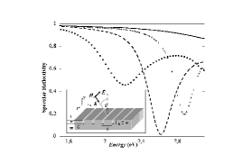
Our results were obtained by the exact modal method, originally developed by Botten et al. botten and
Sheng et al. sheng , for the grating depicted in fig.1,
submitted to a p-polarized wave (electric field perpendicular to the
grooves). Space is divided into three regions: above () and
below () the grating (regions I and III respectively) wherein
the magnetic field is expressed as a Rayleigh plane wave
expansion, and region II of the grating () wherein is
expressed by a modal expansion. The electric field is obtained from by means of Maxwell’s equations.
With for sake of simplicity and , the fields are given by sheng :
where , and . is a linear combination of the eigenmodes , each of them being characterized by its eigenwave-vector . These are solutions of the eigenvalue equation botten ; sheng :
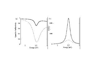
where , and and is the incidence angle. Once the fields are expressed in the three regions, we employ the boundary conditions at the horizontal interfaces and project each resulting equation on two different basis theseJerome . That allows to determine unambiguously the coefficients , , and , for and . Convergency of the solution has been checked by increasing and . Typically, , and only few modes are enough for all considered cases. For very small , only the fundamental mode plays a significant role whereas all the others are strongly evanescent in the grooves. We have tested the method by comparing our numerical results with those obtained by two other accurate numerical methods (RCWA and FDTD) for metallic gratings astilean ; vanlabecke . Fig 1 shows the calculated reflectivity at normal incidence of a silver grating with nm, nm and , and nm. In all cases, we choose such that SPPs at the horizontal interface are never excited in the range of the considered frequencies. The figure shows that noticeably amount of photons can be absorbed by this very small amplitude grating at specific wavelength in the visible spectrum. It is to note that for nm the reflectivity is almost zero at eV ( nm) whereas that of the flat silver plane stays close to 1. This is a reliable quantitative result for AOA.
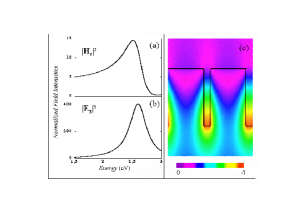
Fig.2 illustrates that the absorption is due to resonances within
the tiny Ag grooves. Indeed, the reflectivity falls are associated
to enhancements of the magnetic and electric fields intensity inside
the grooves. Enhancements of more than two orders of magnitude are
achieved for the electric field while the magnetic field is only
enhanced by a factor . The spatial distribution of the
normalized magnetic field modulus is represented fig.2c considering
the grating with nm and at the resonant energy
eV. One clearly sees that the very sub-wavelength cavities resonate
and absorb a great part of the incident photons.
In order to understand why such strong resonances may occur for such
shallow grooves, let us return to the SPP dispersion of a perfectly
flat metal/vacuum interface. For simplicity we take the dielectric
constant of the metal negative and real ().
The dispersion is given by the explicit well-known relation
, where is the SPP
wave vector parallel to the interface. As it is
known economou , we may distinguish two asymptotic regimes: the
”optical regime” when , and the
”electrostatic regime” when . In the
optical regime, retardation effects play a significant
roleeconomou . The electromagnetic fields at the interface
satisfy and the excited plasmon
has a structure very similar to that of light. On the opposite side
in the electrostatic limit, retardation effects remain
negligible economou . We have and the obtained plasmons have essentially an
electric component. In this context, a relevant physical quantity to
introduce is the dimensionless ratio , where
is the penetration depth of the SPP in the metal, and
is the usual skin depth in the metal of a plane wave
whose wave number is :
while . For a flat interface, . The parameter , satisfies ,
and completely determines the two regimes: in the optical regime, and while in the
electrostatic regime and .
Returning to our grooves with small , we show that the role played by the decrease of down to the nanometer scale, is to displace the dispersion of the mode guided in the cavities, from the optical regime to the electrostatic one, for a given frequency and thus for a fixed value (figure 3). Let us consider the dispersion relation Eq.(1) of the grating in the case of silver and in a range of wave numbers for which values of are typically in the interval (visible range). Here again we neglect the imaginary part of , we will come back to this approximation later. In the case of sub-wavelength values of , it is easy to show that and that the only guided wave in the groove is the fundamental mode whose wave vector is . This mode may satisfy a Fabry-Perot resonance condition when , as for gratings with deep grooveswirgin ; astilean , leading to the cavity resonance we are discussing. The problem is to determine the value of and its dispersion. For large enough and at normal incidence, Eq.(1) may be simplified and factorized, so that the fundamental mode fulfills:
where , . For small values of (which is always verified for sub-wavelength ), we get a simple second degree equation for : . We now introduce the same quantity as for the perfectly flat plane: . Solving the previous second degree equation in we obtain:
| (2) |
where and . Notice that Eq.(2) is an almost exact result which is valid whatever and are, provided that the imaginary part of remains small with respect to its real part, and that . The function satisfies and fully characterizes the behavior of the system. The dimensionless parameter reflects the strength of the coupling between the SPPs propagating on the two vertical walls of the grooves. For , the coupling is weak, whereas at strong coupling .
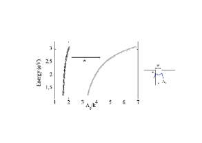
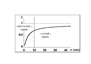
Figure 3 depicts the behaviour of as function of for silver
at cm-1 ( eV, ).
By increasing the coupling of the SPPs via the reduction of the
widths of the cavities, we can fully scan the different behaviour of
the usual SPP, from the electrostatic regime to the optical one,
with a crossover located around nm, and that at a given
frequency. This allows to have a control of the absorption
properties of the grating by a simple choice of geometrical
parameters.
Figure 4 depicts the dispersion of the
fundamental mode, which is analytically given by:
| (3) |
as well as the dispersion obtained by the numerical calculation, for two different values of ( and nm), and for nm. The agreement between the numerical and analytical curves is excellent and shows that as decreases the wave vector of the guided mode increases even though it is excited by the same incident energy. Meanwhile, we know from fig.3 that its penetration depth in the metal becomes much smaller than the ordinary skin depth (). The dispersion relation of the modes in the optical regime can be deduced from Eq. 3 taking and was already discussedastilean ; sobnack ; collin . Reversely, in the electrostatic regime, , and Eq.(3) leads to:
| (4) |
which implies that Fabry-Perot resonances occur for very small values of , correspondingly to those obtained numerically on Fig.1 and Fig.2. The electromagnetic field in the groove is dominated by the electric field, . It is also interesting to notice that since essentially depends on , we may obtain a scaling law using the condition resonance . All grooves with nearly the same ratio will resonate around the same frequency. This is shown on figure 5, for a grating with nm and nm and one with nm and nm.
.
An analytical study of the fields expression
shows that , where
is the amplitude of the total incident field. Considerable electric
field enhancements can thus be obtained inside the grooves with small
. Actually the electrostatic regime is easily obtained provided
that the sub-wavelength cavities are weakly coupled through the
metal, that is to say if the grooves are sufficiently distant
(), otherwise stays around .
Giant enhancements, obtained for large , are numerically
observed: for instance, it is much greater than for nm,
nm and nm at eV ( nm).
Finally, it should be observed that turning on a small imaginary
part of , with , the resonant wavevector also has
an imaginary part . We can show analytically that for
: , where
is the imaginary part of
the SPP wave vector of a perfectly flat surface. The attenuation of
the SPPs along the walls of the cavity is thus more important than
in the case of a single plane surface, for a given frequency.
Nevertheless the depth of our channels is as small as the wave
vector is long to excite the Fabry-Perot like resonance at
. Consequently these modes remain slightly
attenuated over the distance corresponding to the depth of the
channel.
In conclusion, free electron metal surfaces with grooves
of rectangular shape and nanometer dimensions may absorb visible
light of well defined frequencies and lead to extremely high electromagnetic
near-fields. Our calculations suggest that AOA observed on rather
smooth metal films may be due to notches (distorted grain
boundaries) few nanometers deep only. We have pointed out
some geometries that could optimize the near-field to generate
controlled Raman scattering enhancements. Finally, the calculated
enhancements suggest that SERS could also be due to the excitation
quasi-static surface polaritons in the grooves (giving rise to the
so-called ”hot spots”), with
penetration depth much smaller than the usual skin depth.
The authors wish to thank A. Wirgin, Ph. Lalanne and S. Collin for
useful discussions.
References
- (1) E. Ozbay, Science 311, 189-193 (2006).
- (2) K. Tanaka, M. Tanaka, Appl. Phys. Lett. 82, 1158-1160 (2003).
- (3) D.F.P. Pile et al., Appl. Phys. Lett. 87, 061106-1,-3 (2005).
- (4) H. T. Miyazaki, Y. Kurokawa, Phys. Rev. Lett. 96 097401 (2006)
- (5) S. A. Maier, Opt. Exp. 14 1957 (2006).
- (6) Y. Kurokawa, H. T. Miyazaki, Phys. rev. B 75 035411 (2007).
- (7) J. R. Suckling et al., Phys. Rev. Lett. 92, 147401 (2004).
- (8) E. N. Economou, Phys. Rev. 182 539 (1969).
- (9) B. Prade, J.Y. Vinet, A. Mysyrowicz, Phys. Rev. B 44 13556 (1991).
- (10) R. Wood, Phil. Mag. 38, 98-112 (1919).
- (11) O. Hunderi, H. P. Myers, J. Phys. F: Metal Phys. 3, 683 (1973). H. P. Myers, J. Phys. F: Metal Phys. 3, 1078 (1973). H. P. Myers, J. Phys. F: Metal Phys. 6, 141 (1976).
- (12) C. Douketis et al., Phys. Rev. B 51 11022-11031 (1995).
- (13) M. Moskovits, Rev. Mod. Phys. 57, 783-826 (1985).
- (14) A. Otto, Zeitschrift fur Physics A Hadrons and Nuclei, 216, 398 (1968)
- (15) A. Hessel and A.A. Oliner, Appl. Opt., 4, 1275 (1965)
- (16) A. Wirgin, T. López-Ríos, Opt. Comm. 48, 416 (1984), Opt. Comm. 49, 455 (1984).
- (17) M.B. Sobnack et al., Phys. Rev. Lett., 80, 5567 (1998).
- (18) W.C. Tan et al., Phys. Rev. B, 59, 12661 (1999).
- (19) S. Astilean, P. Lalanne, and M. Palamaru, Opt. Comm. 175 265-273 (2000).
- (20) I.R. Hooper and J.R. Sambles, Phys. Rev. B, 66, 205408 (2002).
- (21) E. Popov, N. Bonod, S. Enoch, Optics Express, 15, 4224 (2007).
- (22) L.C. Botten et al., J. of Modern Opt. 28, 1087-1102, and 1103-1106 (1981).
- (23) P. Sheng, R.S. Stepleman and P.N. Sanda, Phys. Rev. B 26, 2907-2916 (1982).
- (24) J. Le Perchec, PhD dissertation, Grenoble (2007), unpublished.
- (25) F.I. Baida and D. Van Labeke, Phys. Rev. B 67 155314 (2003).
- (26) S. Collin, F. Pardo, J. L. Pelouard, Opt. Exp. 15 4310 (2007).