Present address: ]Laboratoire Central des Ponts et Chaussées, Paris, France
Saffman–Taylor instability in a non-Brownian suspension:
finger selection and destabilization
Abstract
We study the Saffman–Taylor instability in a non-Brownian suspension by injection of air. We find that flow structuration in the Hele-Shaw cell can be described by an effective viscosity depending on the volume fraction. When this viscosity is used to define the control parameter of the instability, the classical finger selection for Newtonian fluids is recovered. However, this picture breaks down when the cell thickness is decreased below approximatively 10 grain sizes. The discrete nature of the grains plays also a determinant role in the the early destabilization of the fingers observed. The grains produce a perturbation at the interface proportional to the grain size and can thus be considered as a ”controlled noise”. The finite amplitude instability mechanism proposed earlier by Bensimon et al. allows to link this perturbation to the actual values of the destabilization threshold.
pacs:
47.15.gp, 47.54.-r, 47.55.Kf, 83.80.HjIntroduction – When a low viscosity fluid like air displaces a viscous, immiscible fluid in a thin channel or Hele-Shaw cell, an instability develops at the interface, leading to the formation of fingerlike patterns, called viscous fingers or Saffman–Taylor instability Saffman and Taylor (1958). Since the early work of Saffman and Taylor, this problem has received much attention not only because of its practical importance but also since it represents an archetype of many pattern forming systems Couder (1991); Homsy (1987); Bensimon et al. (1986). Driven by practical and fundamental interests, several viscous fingering studies have lately been extended to non-Newtonian fluids where a wide variety of strikingly different patterns are found McCloud and Maher (1995).
Here, we use the Saffman–Taylor instability in a Hele-Shaw channel as a model system to study the dynamical properties of the interface between a pure fluid and a non-Brownian suspension. This kind of particle laden fluid is known to structure under shear as the particles migrate towards regions of lowest shear and thus change the local viscosity of the flow. As a consequence, this is a fluid with complex evolutive properties. A central question is to understand whether a simple effective continuum description remains valid and how pattern selection and finger stability can be affected by the fluid structuration as well as the discrete nature of the grains.
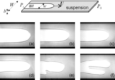
Set-up and characterization of the suspensions – The experiments are performed in an Hele-Shaw cell of length 1 m formed by two 1.5 cm thick glass plates separated by a thin mylar spacer (Fig. 1). The cell thickness can be varied (=0.75 - 1.43 mm) as well as the width of the channel (=2 - 4 cm). The thin channel is initially filled with a non-Brownian suspension that is then displaced by air. The suspensions are formed by spherical polystyrene beads from Dynoseeds suspended in a Silicon oil. We use different grain diameters =20, 40, 80 or 140 m, their density is =10501060 kg/m3. The grains are dispersed in a modified Silicon oil (Shin Etsu SE KF-6011) such as to obtain density matching at a value =1070 kg/m3. We measured the viscosity of the pure fluid = 191 mPa.s as well as its surface tension =21 mN/m at 21∘C. The fact that the particles and the suspending fluid are density matched allows us to control the volume fraction over a wide range. Here we work with volume fractions below 40 which allows to avoid jamming problems and wall slip occurring at higher volume fractions.
A constant overpressure is applied at the inlet whereas the outlet is maintained at atmospheric pressure. The advancing finger tip is observed using a CCD camera mounted on a movable system which allows a manual tracking of its position. The camera is coupled to a microcomputer for direct image acquisition. Note that in this configuration, the applied pressure gradient is not constant and therefore, the finger accelerates when propagating through the cell. We verified that this acceleration is slow enough and does not influence the observed finger properties (i.e. for a given tip velocity, we have no dependence on the applied overpressure).
Finger width selection – For Newtonian fluids, the width of the viscous fingers is determined by the capillary number , the ratio of viscous to capillary forces; being the finger velocity, the viscosity and the surface tension of the fluid. More precisely, the relative finger width is a function of the dimensionless control parameter , which involves the cell aspect ratio. The mean flow (averaged over the cell thickness) is governed by Darcy’s law which links the fluid velocity to the pressure gradient and far away from the finger, reduces to: where is the applied pressure gradient.
Therefore, by analogy with Newtonian fluids, we seek to establish the relevant control parameters of the injection process. A first step will be to measure the suspension viscosities as a function of volume fraction. Since we want to evidence the influence of structuration effects due to the confinement in the Hele – Shaw cell, we will compare the viscosities obtained from the commercial rheometer to those extracted directly from Darcy’s law in the Hele-Shaw cell.
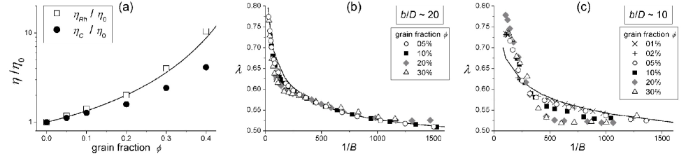
The suspension viscosities (for =40 and 80 m) were obtained by rheological measurements using a double Couette geometry rheometer (Haake-RS600) of gap width 2*0.25 mm and mean radius 20 mm. The gap width being small with respect to the radius, the velocity profiles in the gap can be considered as linear. In the range of shear rates tested (=0.1 - 100 s-1) corresponding also to the typical shear rates of the Hele-Shaw experiments, the suspensions behave as a Newtonian fluid with a viscosity independent of the grain diameter and well described by models used in recent literature (as for example Zarraga et al. Zarraga et al. (2000)) (see Figure 2a open symbols). These results confirm the absence of aggregation in the range of volume fractions considered.
Now we investigate the rheology of our suspensions directly in the Hele-Shaw cell. To do so, we systematically established a Darcy’s law for all suspensions and cell geometries we have considered. The details of the procedure can be found in Chevalier et al. (2006, 2005). The results indicate the existence of an effective viscosity parameter specific for flow in a Hele-Shaw cell . In all the studied configurations, this viscosity was found to be independent of the cell geometry (i.e. and ) as well as the grain diameter and is only function of volume fraction .
We found for increasing an increasing deviation of from the corresponding rheometer viscosity (figure 2 a close symbols). The fact that is lower than can easily be explained by the effect of flow structuration due to confinement. It is well known that particles migrate to zones of low shear rate Leighton and Acrivos (1987), here in the middle of the gap. Therefore, the flow profile should deviate from an ideal parabolic profile and evolve towards a flatter profile Lyon and Leal (1997), independent of and solely dependent on . A steady profil is only reached after a certain flow distance below which we do not consider our experiments. In addition we also verified that the grains in the suspension do not alter the surface tension.
We systematically studied the selection of the finger width for stable fingers different values of the volume fraction . Typical results are displayed on figure 2b and c. The solid line represents the pure fluid measurements and thus corresponds to the classical result for Newtonian fluids. Importantly, we choose to use to define the control parameter . We notice that this choice rescales our data when the ratio between the cell thickness and the grain diameter is larger then approximatively 10. Below significant deviations from the classical result appear: fingers are slightly larger for low , thinner for intermediate - this narrowing is more important for large volume fraction - and then eventually will join the classical curve for larger values of . In all cases, for large 1/B the asymptotic value 1/2 for the relative finger width seems to be recovered.
So far, we were not able provide any fully satisfactory argument to explain the deviation from the classical results. One might however speculate that effects like a depletion of grains in front of a receding meniscus Tang et al. (2000) (where 3D effects become important) would lead to a lower viscosity at the finger tip and thus induce a finger narrowing as observed for shear thinning fluids Lindner et al. (2002). One could also consider other effects like normal stresses existing in granular suspensions Zarraga et al. (2000), that have been shown to increase the finger width Lindner et al. (2002) and might thus eventually be responsable for the fact that the narrow fingers get wider again and stem to the classical results at a higher control parameter.
Finger destabilization – When increasing the finger velocity and thus the control parameter one observes a destabilization of the fingers. First, the sides of the fingers start to ondulate and when the velocity is further increased, the finger gets unstable by tip splitting. A typical evolution of such a destabilization can be seen on figure 1. Note that in some cases asymmetric fingers (not shown here) have been observed like predicted by Ben Amar et al. BenAmar and Brener (1996).
This destabilization scenario is also observed in classical Saffman–Taylor experiments and has so far been attributed to the noise in the cell hence making it difficult to predict exact values for this instability threshold Park and Homsy (1985); Tabeling et al. (1987). In the case of our suspension, we identified the instability threshold for different volume fractions and cell thicknesses. To have a reproducible and objective method of detection, we have measured by image processing the fluctuations of the finger width and detect when this quantity starts to increase. The onset of fluctuation growth defines the stability threshold and therefore, the critical control parameter .
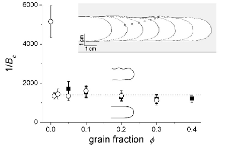
When the values of are plotted against the grain fraction (see figure 3) for two different set ups (different cell thickness, same grain size), we surprisingly find that as soon as a small amount of grains (as small as 1 ) is added, the value of the threshold drops strongly and thereafter varies weakly with the grain fraction (if not constant within the experimental uncertainties). Note that we found different values for the threshold in pure fluid for the different configurations and thus two different intrinsic levels of noise. However in the presence of grains the value of the threshold is well defined.
When looking closer at the destabilization scenario of a single finger (figure 3 inset), one observes that perturbations nucleate close to the finger tip and are then advected to the side of the finger. A possible explanation for this destabilization mechanism was given by Bensimon et al. Bensimon et al. (1986). They propose that a perturbation would nucleate at the finger tip, where the normal velocity is the highest and where the growth rate (given by the linear stability analysis of the Saffman–Taylor problem Chuoke et al. (1959)) is largest. While the finger continues to grow, the perturbation is advected to the side of the finger where the normal velocity goes to zero and thus, the perturbation growth stops. In the process of advection, the perturbation is stretched and consequently, its amplitude is decreased. For a given control parameter , one needs a given, finite amplitude of the initial perturbation to be able to obtain a perturbation with a given final amplitude when the side of the finger is reached. More quantitatively, Bensimon et al. derived the following relation that describe the ”finite amplitude instability”:
| (1) |
| N config. | ||||
|---|---|---|---|---|
| 1 | 80 m | 0.84 mm | 20 mm | 1210 |
| 2 | 20 m | 0.75 mm | 40 mm | 3220 |
| 3 | 40 m | 0.75 mm | 40 mm | 2670 |
| 4 | 80 m | 0.75 mm | 40 mm | 1600 |
| 5 | 80 m | 1.43 mm | 40 mm | 1530 |
| 6 | 140 m | 1.43 mm | 40 mm | 1150 |
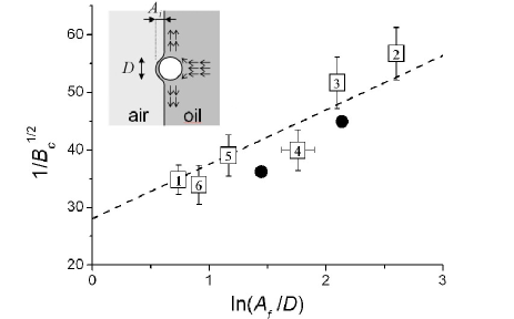
In the following, we will test if the destabilization observed in our situation can be described by the previous mechanism and if the existence of grains in the viscous fluid can be directly linked to the instability onset. A first indication is that we observe a destabilization threshold hardly affected by an increasing grain fraction; the above described mechanism is indeed independent of the wavelength of the perturbation which one might be tempted to link to the grain fraction. In their theoretical approach, Bensimon et al Bensimon et al. (1986) consider the final amplitude to be proportional to the channel width . For our analysis, we directly use the value of the fluctuations of the finger width observed at . Those are of course via the finger width proportional to and we consider a sinusoidal form of the fluctuations leading to . A natural assumption is to relate the amplitude of the initial perturbation to the grain diameter : . In table 1 we sumarize the results obtained for different grain sizes and different cell widths . When we plot as a function of obtained for , different cell geometry and different grain sizes (Fig. 4), we obtain a very satisfying quantitative agreement with the theoretical result of Bensimon et al when the initial perturbation is taken to be: .
Now, to provide a rational justification for our choice for the initial perturbation, we need to show that a particle approaching a free interface at a stagnation point flow, as is the case of the finger tip, would indeed be able to deform this interface with the correct amplitude. Hoffman Hoffman (1985) and Montiel et al. Montiel and Alexander-Katz (2003) established a link between the free interface amplitude of perturbation and a capillary number defined on the scale of a particle: . In our case, the range of capillary numbers would be =5*10-3 - 2*10-2 and thus, the corresponding values for the amplitude of the perturbation are of order of . Therefore, this is indeed in good agreement with our choice of the amplitude of the initial perturbation and it confirms the validity of the theoretical prediction of Bensimon et al Bensimon et al. (1986). This is a striking emergence of the particulate nature of the suspension, the grains acting here as a controllable noise amplitude.
Conclusion – We have shown that the characteristics of the stable Saffman – Taylor fingers invading a non-Brownian suspension, are mainly determined by the effective properties of the suspension in the cell far from the fingers. The structuration effects of the confined particulate flow can simply be taken into account by an effective viscosity, which allows to rescale the width selection curve onto the classical results. However, when the grain size becomes important compared to the cell thickness, systematic deviations from the classical result are evidenced.
We also studied the destabilization of the Saffman–Taylor fingers and we showed that individual grains perturbe the interface between the air and the suspension and lead to a premature destabilization of the fingers. The threshold of instability is found to match quantitatively the theoretical prediction of Bensimon et al.. To our knowledge this is the first time that an experiment allows to control the initial ”noise” in the cell and thus to investigate a mechanism of finite amplitude instability directly.
Recently a number of studies have reported oscillations of the finger width, observed for example for low capillary number Moore et al. (2002) or fixed perturbations of the cell thickness Torralba et al. (2006). A more close characterization of the oscillations resulting from the premature destabilization in our system might reveal similarities between the different systems.
Acknowledgements.
We wish to thank Michel Cloître and Fabrice Monti for help with the rheological measurements, Daniel Bonn for for help and advice with the experimental set-up and José Lanuza for technical assistence.References
- Saffman and Taylor (1958) P. Saffman and G. Taylor, Proc. R. Soc. A 245, 312 (1958).
- Couder (1991) Y. Couder, Growth patterns: from stable curved fronts to fractal structures (Plenum press, New York, 1991).
- Homsy (1987) G. Homsy, Ann. Rev. Fluid Mech. 19, 271 (1987).
- Bensimon et al. (1986) D. Bensimon, L. Kadanoff, S. Liang, B. Shraiman, and C. Tang, Rev. Mod. Phys. 58, 977 (1986).
- McCloud and Maher (1995) K. McCloud and J. Maher, Physics Reports 260, 139 (1995).
- Zarraga et al. (2000) I. E. Zarraga, D. A. Hill, and D. Leighton, J. Rheol. 44, 185 (2000).
- Chevalier et al. (2006) C. Chevalier, M. Ben Amar, D. Bonn, and A. Lindner, Journal of Fluid Mechanics 552, 83 (2006).
- Chevalier et al. (2005) C. Chevalier, A. Lindner, and E. Clément, Pattern formation by injection of air in a non-Brownian suspension (Balkema, 2005).
- Leighton and Acrivos (1987) D. Leighton and A. Acrivos, Journal of Fluid Mechanics 181, 415 (1987).
- Lyon and Leal (1997) M. Lyon and L. Leal, J. Fluid Mech. 363, 25 (1997).
- Tang et al. (2000) H. Tang, W. Grivas, D. Homentcovschi, J. Geer, and T. Singler, Phys. Rev. Lett. 85, 2112 (2000).
- Lindner et al. (2002) A. Lindner, D. Bonn, E. C. Poire, M. Ben Amar, and J. Meunier, Journal of Fluid Mechanics 469, 237 (2002).
- BenAmar and Brener (1996) M. BenAmar and E. Brener, Physica D 98, 128 (1996).
- Park and Homsy (1985) C. Park and G. Homsy, Phys. Fluids 28, 1583 (1985).
- Tabeling et al. (1987) P. Tabeling, G. Zocchi, and A. Libchaber, J. Fluid Mech. 177, 67 (1987).
- Chuoke et al. (1959) R. Chuoke, P. v. Meurs, and C. v. d. Poel, Pet. Trans. AIME 216, 188 (1959).
- Hoffman (1985) R. L. Hoffman, Journal of Rheology 29, 579 (1985).
- Montiel and Alexander-Katz (2003) R. Montiel and R. Alexander-Katz, Journal of Polymer Science Part B-Polymer Physics 41, 1362 (2003).
- Moore et al. (2002) M. Moore, A. Juel, J. Burgess, W. McCormick, and H. Swinney, Phys. Rev. E 65, 030601(R) (2002).
- Torralba et al. (2006) M. Torralba, J. Ortin, A. Hernandez-Machado, and E. C. Poire, Physical Review E 73 (2006), part 2.