Self-organized surface nanopatterning by ion beam sputtering
To appear in Lecture Notes on Nanoscale Science and Technology, edited by Z. Wang (Springer, Heidelberg).
1 Introduction
Nanotechnology and Nanoscience are inducing a turning point in fields from Condensed Matter Physics and Materials Science to Chemistry and Biology. This is due to the new types of behaviors and properties displayed by nanostructures, ranging across traditional disciplines Hodes_2007 . Interest in these systems is also triggered by the possibility of characterizing them morphologically by scanning probe microscopy techniques (SPM) Binnig_1986 and by the advance in surface structure determination methods. Within this more specific context, there is an increasing need for the development of techniques and methods for the patterning of materials at the nanoscale. Moreover, this goal must be achieved in an efficient, fast and low-cost manner for eventual technological applications to be compatible with mass-production. In addition, the processes involved should allow control over the size, shape and composition of the nanostructures produced.
Within this trend, there is also a great interest in developing methods for producing confined nanostructures, which would display quantum confinement effects, on surfaces. Of especial interest would be those systems in which these surface nanostructures form an ordered pattern.
Among the technological issues behind surface nanostructuring, we can highlight:
-
•
New advances in magnetic storage technology Shen_2002 .
-
•
The production of surfaces and thin films with well controlled shape at the nanoscale for applications in catalysis Zaera_2002 .
-
•
The design of nanoelectronic devices based on the use of quantum devices Amirtharaj_2002 , for example for developing multispectral detector arrays by exploring novel detection techniques, nanopatterning and control of the production of self-assembled quantum structures.
-
•
The possibility of functionalization of these surface nanostructures that allows the selective attachment of specific molecules Kasemo_2002 .
-
•
The design of nanosensors based on surface-enhanced Raman scattering effects (SERS) or localized surface plasmon resonance Yonzon_2005 .
-
•
The use of these nanopatterned surfaces as templates to transfer these patterns to highly-functional surfaces Azzaroni_2004 that can not be patterned directly. Also, the use of these patterns as templates can be applied to reduce fabrication steps or to increase productivity.
There are different approaches for surface nanostructuring. Among the so-called top-down methods we can mention lithographic techniques (nanoimprint lithography Guo_2007 , nanosphere lithographic techniques Yonzon_2005 , soft lithographic methods Xia_1997 and focused ion beam (FIB) techniques Moore_1997 ). Other approaches are based on the use of SPM to induce nanostructures on a surface through different processes such as tip induced oxidation Calleja_1999 , tip induced e-beam lithography Soh_2001 , dip-pen nanolithography Mirkin_2001 , the application of strong electric fields between tip and sample Li_1989 , and the mere use of the probe as a stylus or pen to write at the nanoscale on the sample surface Sohn_1995 . However, these methods present different limitations, such as proximity effects, low resolution or the need of parallel processing because of the (relatively) small processed area. In the case of SPM-based techniques, mainly Scanning Tunneling Microscopy (STM) and Atomic Force Microscopy (AFM), the use of an array of tips aims to compensate for this last limitation.
Potential alternatives to overcome the limitations of the top-down approach are provided by bottom-up methods, which are mainly based on self-organized processes. In this field, most efforts have been traditionally focused on the production of self-organized nanostructures occurring in semiconductor heterostructure growth Stangl_2004 ; Teichert_2001 in which strain relief mechanisms take place. This simpler method seems to be a highly cost-efficient route towards large-scale arrays of nanostructures, although it presents some disadvantages such as enabling less control on structure size and shape than other methods, and the need to work under ultra-high vacuum conditions.
In recent years, special interest is being paid to the study of self-organized nanopattern formation on surfaces by ion beam sputtering (IBS) techniques Facsko_1999 . In general, two types of surface nanostructures can be induced by IBS: (a) nano-ripples and (b) nanodots. In both cases, the pattern formed by these nanostructures can have dimensions ranging from a few up to hundreds of nanometers. These patterns can be produced on different materials, amorphous or crystalline, in just a few minutes and over areas of several square millimeters. The diversity of materials processed and the similar morphologies obtained indicate the universality of the process. In addition, it allows the eventual control of the induced nanostructures by changing the sputtering parameters, such as ion energy, dose, substrate temperature, ion incidence geometry, etc. Moreover, it can be used to produce functional surfaces and isolated structures Valbusa_2002 . Thus, IBS becomes a versatile, fast and cheap technique for surface nanopattering.
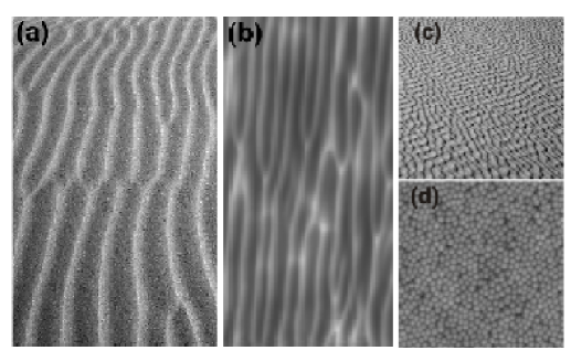
The ability of IBS to induce submicro-structures on surfaces was reported more than forty years ago by Navez et al. Navez_1962 . In that work, they reported the production of periodic nanoripples on glass surfaces. In Fig. 1b we show ripples obtained on a silicon surface immersed in an argon plasma. These ripples indeed remind us of those formed on sand dunes by the wind or on the sand bed close to the water edge by the water flow (Fig. 1a). As we will show below, this similarity is more than merely visual as the theories dealing with both types of (macro and nano) structures share many conceptual aspects. In the pioneering work of Navez and coworkers the authors did report important morphological observations, such as the change of the ripple orientation when the ion incidence polar angle is larger than a threshold value. Later, similar findings were reported for other materials, that have been reviewed elsewhere Carter_2001 ; Makeev_2002 ; Murty_2002 ; Valbusa_2002 . Usually, the length scales involved in these patterns lie in the sub-micrometer scale, rather than in the nanometer scale. Moreover, the traditional field for ripple applications had been that of optical gratings Johnson_1979 . From the theoretical point of view, the first advances for understanding IBS nanostructuring was made by Sigmund Sigmund_1973 as he showed that local surface minima should be eroded at a faster rate than local maxima (i.e. the sputtering rate depends on the local surface curvature), leading to a surface instability, which is the origin of the nanostructuring process. Based on this work, Bradley and Harper proposed later the first continuum model describing ripple formation Bradley_1988 . In recent years, other continuum models have been proposed Cuerno_1995 ; Makeev_1997 ; Park_1999 . These models account for different experimental behaviors, such as the presence of absence of saturation for the ripple amplitude, ripple orientation, ripple dynamics as well as the existence or not of kinetic roughening.
However, a clear turning-point occurred when in 1999 Fackso and coworkers Facsko_1999 reported on the IBS production of GaSb nanodot patterns, which also display short-range order. This work shifted the focus of the research to the nanometer scale. The evident technological implications Chen_2002 ; Lindner_2000 of the possibility to induce nanostructures on semiconductor surfaces on a relatively large area (several square millimeters) and in just a couple of minutes motivated further interest in these processes. Thus, nanodot production has been reported in different materials such as InP Frost_2000 , Si Gago_2001 , Ge Ziberi_2006 , etc. With respect to the theoretical understanding of the nanodot IBS production, the theories must share most of the concepts with those developed for IBS induced ripples. An example is shown in Figures 1c and d, in which “dotted” structures formed both on sand dunes and IBS nanodot structures are displayed. Once more, this similarity appears that, rather than being just visual, is, in fact, deeper as will be showed in Sec. 4.3.
The production of dot patterns has changed the focus of the theoretical investigations. Now, for dot patterns the interest is more directed towards dot size and pattern order because of their technological implications. In the first case, it is interesting to know how the dot size changes with the different IBS parameters, specially ion energy, target temperature and sputtering time (i.e., fluence). In the second case, it is necessary to know under which conditions the pattern order is enhanced. Thus, issues such as pattern wavelength coarsening and order enhancement have become relevant. Accordingly, new theoretical descriptions have been proposed Castro_2005 ; Chen_2005 ; Facsko_2004 ; Kahng_2001 ; Makeev_2002 ; Munoz_2005 ; Vogel_2005 .
The aim of this chapter is to give an overview of ripple and dot IBS nanopatterning that focus specially on those issues that remain open or, at least, ambiguous. This will be more evident for the case of nanodot patterns on amorphizable targets due, probably, to their relative novelty. In fact, we will treat specially the case of this type of patterns since previous reviews were devoted mainly either to ripple patterns Carter_2001 ; Makeev_2002 or to the case of metals Valbusa_2002 . Stress will be paid to review the observed behaviors and the predictions of the main existing continuum models. When possible, we will contrast the experimental data with the theoretical predictions.
The chapter will be divided as follows. After this introduction and for the sake of completeness, we will present the basics of the Physics behind the ion sputtering process. Then, we will give an overview of experimental findings on surface nanopatterning by IBS on amorphous materials and single-crystal semiconductors. We will review briefly the results for the special case of single-crystal metal surfaces as they were already extensively reviewed by Valbusa and coworkers Valbusa_2002 . In the next section a review of the theoretical studies of these processes will be presented, with special emphasis on the various continuum models proposed so far. In the last section of the chapter we will propose possible applications of these nanopatterns and, finally, we will state the issues that still remain open, from our point of view, both theoretically and experimentally.
2 Fundamentals of ion sputtering
2.1 Introduction to ion sputtering
Physical sputtering is defined as the removal of atoms from a solid surface due to energetic particle bombardment. This phenomenon was first reported by Grove Grove_1852 in 1852, although others had probably noted the effect while studying glow discharges. Grove studied the discharge generated by the tip of a wire positioned close to a polished silver surface and noted a ring-like deposit onto the silver surface when it was acting as an anode in the circuit. However, it was not until the early 1900 s when the effect was attributed to the impingement of positive ions accelerated towards the cathode by the electrical field Stark_1908 . The sputtering process resembles the macroscopic sandblasting process but with ionized atoms instead of sand grains as bombarding species. In fact, the erosion efficiency with the incident angle of the abrasive particles Finnie_1995 is analogous to that observed in ion sputtering experiments.
The sputtering process is important both from a fundamental as well as a practical point of view. On the one hand, the understanding of the process is relevant to describe the basic interactions of ions with matter. On the other hand, as shown below, the process has found a broad range of applications. The improvement in experimental methods, as well as in the theoretical description of the process, has promoted the rapid maturation of the field during the last decades.
2.2 Applications of ion sputtering
The applications of ion sputtering to Surface Science and Technology are very diverse Murty_2002 . First, the removal of atoms from the surface can be used as an effective method for surface cleaning Taglauer_1990 . This may be aimed, for example, at removing the undesirable contamination layer present on a surface (mostly containing oxygen and carbon impurities), which may affect the intrinsic electrical or optical properties. This cleaning process may be crucial for the optimal performance of a semiconductor device Schubert_2005 .
The sputtered material from the target can also be transferred to a substrate for thin film deposition (sputter deposition methods) Rossnagel_2003 . This application of sputtering was first addressed by Plücker in 1958 Pluecker_1958 after he observed the formation of a platinum film inside a discharge tube with a metallic mirror-like appearance. Sputter deposition is a non-equilibrium process where material ejection occurs at hyperthermal energies (in the few eV range) Stuart_1969 . This energy range is much higher than in thermal evaporation methods, leading to coatings with better properties (higher density, etc.). The sputtering phenomenon is the base of many industrial coating activities, being scalable from small pieces up to processing of large areas (it is commonly used to coat structural window panels). It is relevant for the development of magnetron sputtering techniques Rossnagel_2003 , where high erosion/growth rates are obtained by confining the plasma discharge close to the cathode through a magnetic field.
The ejected particles during sputtering can also be identified for compositional analysis of the target material. This technique is known as secondary ion mass spectrometry (SIMS) Zalm_1994 and is based on the principle that a small fraction of the sputtered particles are ionized. These particles are guided and detected by means of a mass spectrometer and provides very high depth resolution (in the monolayer range) and elemental sensitivity down to parts per billion (ppb).
The progressive etching of the target material through sputtering finds usage for sample thinning. Such a process is often incorporated into specimen preparation for transmission electron microscopy (TEM) where, after mechanical milling, grazing incidence ions impinge onto the remaining part of the sample until the desirable electron transparency is achieved (a few hundreds of nm for the energies commonly used for imaging). The progressive erosion of the surface is also an extended route for depth profiling with surface analytical techniques by a sequence of sputtering and analysis steps Oechsner_1984 . In this case, high depth-resolution can be achieved by erosion depths of a few monolayers but, as may occur in SIMS, by-products of ion bombardment such as atomic intermixing or preferential sputtering deteriorate the resolution of the analysis.
The application of material etching through sputtering is more extended in the fabrication of integrated circuit devices. Here, pattern or feature formation taking part in implementing the design of the device is imprinted onto the substrate in several steps of ion beam etching or “drilling”. This submicron architecture is defined by means of lithography, masks or FIB methods.
Finally, as mentioned in the Introduction, sputtering can be used to alter the surface morphology due to its dependence on the local surface curvature Valbusa_2002 . In this case, depending on the conditions (angle of incidence, energy, etc.), it can induce either surface smoothening or roughening. These competing processes may be used to design the surface geometry required for certain applications. For example, smooth surfaces are needed in optical components such as mirrors or lenses Frost_2004 or for tribological surfaces. For this purpose, sputtering should preferentially erode prominent topographies by, for example, grazing incidence bombardment, or promote ion-induced surface diffusion processes. On the contrary, roughening of a surface may enhance, for example, the surface activity (more effective surface is available), catalytic or other chemical processes, as well as control the biological response of the surface. Also, the competition between roughening and diffusion can lead to the evolution of correlated features and induce the spontaneous formation of a regular pattern Valbusa_2002 . This self-organized pattern formation is the main subject of this chapter and will be described in detail in subsequent sections.
2.3 Quantification of the sputtering process
The sputtering process depends on several parameters such as the nature of the target, type of ion, ion energy, incidence angle, ion flux (rate of incoming ions towards the target per unit area) and total fluence (or dose). For quantification of the ion-target interaction as a function of the different parameters, early investigations focused on the average number of target atoms ejected per incident ion. This magnitude is defined as the total sputtering yield (S) or, if measured in terms of a specific energy or angular interval, it is described as differential yield. However, there are other observables such as the effect on surface morphology or ion induced lattice damage that can be used for quantification of the sputtering effect. The understanding of the latter effects has only been possible with the recent development of proper characterization tools for surface imaging or structure determination.
For multicomponent targets, the yield for each particular element should be taken into account. When the difference in S among species in the substrate is large, a preferential sputtering of the target elements with greater S occurs. This implies that the composition of the sputtered particles differs from that of the multi-component target and, as a consequence, induces an enrichment of the low-S component at the outermost layers of the target.
2.4 Experimental measurements of the sputtering yield
For a given ion and energy, there is no direct relation between the atomic number of the target element and the resulting S Andersen_1981 . However, there are general experimental observations on the behavior of S as a function of other sputtering parameters, mainly ion flux, energy and incidence angle. An important experimental observation is that ion erosion occurs even in the limit of low ion flux and that S is independent of the incoming flux. In addition, for a given projectile, S varies rather smoothly with incident ion energy until reaching a broad maximum (in the 10-100 keV range) and, then, gradually dropping to zero for very high energies (in the MeV range) Zalm_1986 . This behavior is found for almost all projectile-target combinations. The variation of S with the ion incidence angle, , which is measured with respect to the surface normal, is considerable and increases from normal to oblique incidence until reaching a maximum around 60-70∘, and then sharply dropping for glancing incidence angles Oechsner_1975 . The increase of S with is explained by the higher energy deposited in the surface region, a simple geometrical projection giving a relation. The reduction of S at glancing incidence is due to the increase in the reflection of the incident ions Witcomb_1974 . The variation of the sputtering yield with the angle (relation between the maximum sputtering yield and the value at normal incidence) depends strongly on the ion/target combination, being larger for light ions. The general trends of S as a function of ion energy and incidence angle are illustrated in Fig. 2.

It has been reported that S can considerably increase with ion fluence Andersen_1981 . The steady state is reached only after the target has been eroded to a depth of the order of the projected ion range (maximum penetration depth of the ions in the direction normal to the surface). Obviously, this observation could be explained by the ion induced modification of the subsurface due to ion implantation. However, the analysis of the ejected particles also suggests that the yield increase may come from a mechanism of gas trap release Wittmaack_1984 .
Regarding other parameters, it is generally thought that the temperature, apart from small changes in the sublimation energy, does not influence sputtering behavior significantly. Regarding crystallinity, the value of S may differ significantly as a function of energy among single crystal, polycrystalline or amorphous targets of the same element. In single crystals, the yield may also depend on the surface orientation. A satisfactory explanation for these behaviors relies on the concept of channeling (the collision probability is reduced if the ion is guided through a crystal channel), the contribution of this effect being less important in the low-energy range (below a few keV).
In the previous description, energetic monoatomic particles impinging on the target surface have been considered. This is typically the case of sputtering experiments with noble gas ions. However, the sputtering process can be further complicated when the incoming ions react chemically with the target species or by bombardment with polyatomic or molecular ions. In the first case, chemical sputtering may also contribute to the increase of S by formation of volatile compound products Roth_1983 . An example of this process has been observed by the increase of S during bombardment of Si with F or Cl ions as compared with the values obtained for noble gas ions bombardment Tachi_1986 . Conversely, when a non volatile compound forms by reaction of the incoming ion and the target element (for example, SiO formation by O bombardment of Si), the value of S is generally reduced. In the case of polyatomic or molecular ions, it should be considered that the molecules fragment upon impact and S should account for the relative contribution of the individual constituents. In this case, a fair approximation considers that the individual ions have the same velocity as the incoming molecule and transfer their energy independently to the surface.
Regarding the emitted particles, the spatial distribution of sputtered atoms is described generally as a cosine distribution. However, as a function of energy, this distribution can change into an under-cosine to over-cosine for low or high ion energy, respectively, or can be somehow more directional if the incident particle is inclined at a high angle with respect to the surface normal Okutani_1980 . Usually, the direction of the sputtered cone is opposite to the incident direction and is thus called a forward-peaked distribution.
Because of the energetic nature of the sputtering process, emitted atoms tend to have energies well exceeding the thermal energy that would be consistent with the target temperature. The energy of the sputtered particles is typically peaked at a few eV and has a long tail that falls as and goes up to the order of the incident ion energy Stuart_1969 . The peak or average kinetic energy depend strongly on the mass of the target atom, as well as on the energy and mass of the incident particle.
2.5 Theory of sputtering
The many-body considerations of the sputtering process pose a formidable challenge to theoreticians. The first models to explain the sputtering process at atomic scale were based in terms of evaporation from a hot spot, i.e., “thermal spike” Stark_1908 . Although the angular distribution of sputtered atoms follows the distribution from a liquid phase and the presence of thermal spikes has been described by Molecular Dynamics (MD) simulations DiazdelaRubia_1987 , this mechanism gives very low S values due to the short-lived nature of the spikes DiazdelaRubia_1987 and it can not account for the flux independence in the sputtering yield.
The theoretical understanding of ion sputtering processes was considerably improved by the introduction of collision cascades. This advance was achieved through a better description of the ion-solid interaction, which was triggered by the building of particle accelerators in the 1950-60 s. When an energetic ion penetrates the surface of a solid target, it travels through the solid losing its energy through collisions with the nuclei and electrons of the target atoms. The range (maximum penetration depth) of the ions can be determined to a good approximation considering the nuclear () and electronic () stopping independently Nastasi_1996 . Except for light ions (H, He), the nuclear stopping dominates at low energies (below a few keV) since the ions get closer to the atom. If the energy transfer to the target atoms is larger than the threshold given by the displacement energy, lattice displacements take place, which precisely occurs mostly when nuclear stopping dominates the energy losses.
The concept of nuclear stopping was thus used by Sigmund Sigmund_1969 to develop a linear cascade model for sputtering. Here, the projectile shares its kinetic energy with target atoms initially at rest in a series of random binary collisions, a process in which fast recoils are created. The recoils knock on other target atoms creating a collision cascade in which more atoms are in motion, but progressively with slower speed. If the energy is deposited in the near surface region, atoms located close to the surface may gain sufficient energy and the appropriate momentum to leave the surface and be sputtered away. The collision cascade occurs in a time interval of picoseconds after the impact, when the recoil energies at the edges of the cascade have come below the threshold of displacement energy (of the order of a few tens of eV). The cascade is damped out by energy dissipation through several mechanisms, such as creation of phonons.
By assuming a Gaussian energy distribution centered at the ion range, an analytical expression for the sputtering yield, S, can be deduced as follows
| (1) |
Here, is the target atom density, is the binding energy of a surface atom and contains material and geometric parameters. The product represents the energy loss per unit length as the ion travels in the target. Sigmund’s theory accounts satisfactorily for many of the observations in amorphous or polycrystalline elemental target materials, like the angular and energy dependences of S, as well as the angular and energy distributions of the sputtered particles. However, it is a continuum theory and, therefore, it does not address inherent inhomogeneity of materials, it can not be applied to crystalline structures since it neglects channeling effects and, finally, it does not consider other relevant issues such as the starting surface morphology. In addition, purely repulsive forces between the ion and the target atoms are only valid for ion energies above a few keV.
The correlation of sputtering with the surface morphology is a crucial issue for the content of this chapter. The effect of micro-rough surfaces was already posed by Sigmund in 1973 Sigmund_1973 . Differences in energy deposition, which are induced by topographical features, may cause a significant reduction of the local sputtering yield at local maxima and, inversely, an increase at local morphological minima. As a consequence, small irregularities on a relatively smooth surface may result enhanced by ion bombardment. This implies that microscopically flat surfaces are unstable under high-dose ion bombardment unless atom migration acts as a dominating smoothing effect. Conversely, sharp cones appear to be surprisingly stable under bombardment leading to surface nanostructuration by IBS. This prediction is the key-stone for the theoretical understanding of roughening or pattern formation induced by IBS, as will be shown in following sections.
Regarding the fundamental description of the sputtering process, the shortcomings of the linear theory have been addressed by the development of computer simulations, providing a direct view of the collision events and incorporating the role of intrinsic material properties. In this case, discrete systems are considered where the ions and target atoms interact in a deterministic way, like in MD simulations, or in a random nature, like in the case of binary collision approximation (BCA). In these models, the interaction is driven by repulsion forces that determine the ion trajectory in the solid. In the BCA method the interaction is treated sequentially until the energy of the projectile and recoils are thermalized. This method was implemented in the TRIM code Ziegler_1985 ; Ziegler_2006 , where a screened Coulomb potential is considered for faster computation. The BCA is valid when the individual collisions are separated in space (fulfilled only for energy above a few keV) and fails when there is cascade overlap, as occurs for low ion energies. In this regime, attractive forces among the particles become more relevant. Even at high energy, the BCA does not provide good description of the collision cascade as the particles slow down.
In the low-energy range, a proper description should consider the simultaneous movement of the projectile and recoils. Since typical processes during sputtering occur in the picoseconds regime, they can be properly described by MD simulations. In this way, experimental observations of crystalline targets have been successfully reproduced, such as the yield as a function of energy or the angular distribution of sputtered atoms Harrison_1988 . However, MD calculations are time consuming in terms of computation and the interaction potential may not be accurate. In addition, the rather small length scales as well the short temporal window analyzed in MD simulations preclude a dynamical description of the sputtering process by MD and make necessary the implementation of Monte Carlo simulations.
2.6 Experimental considerations for ion sputtering
There are many considerations that should be taken into account for precise and reproducible sputtering experiments. The large number of parameters involved and the variety of experimental configurations may imply a large dispersion of results that makes it difficult to present an unified picture. As an illustration of this complexity, most experiments for the determination of S before the 1970 s are not reliable since they were not done under sufficient vacuum conditions Murty_2002 . Most experiments of surface nanostructuration by ion beam sputtering are done by means of low-energy broad ion beam guns (Kaufman, cold cathode, hollow cathode, etc.), medium-energy ions from ion implanters, focused ion beams (FIB) or directly by plasma immersion of the target. In most cases, ion beams are generated by a glow discharge and then extracted by means of proper beam optics. The nature of the discharge as well as the beam optics will define the range of ion flux and the ion energy that can be achieved. In all cases, several considerations should be taken into account such as energy spread, ion flux, vacuum environment or the eventual presence of multiple charge or mass ions. Moreover, a precise knowledge of the irradiation dose is required (direct ion current measurement with a Faraday Cup, collecting the sputtered material from the target or by measuring the etched volume by masking the target). Other relevant issues may be the unintentional temperature increase induced during the ion bombardment (target cooling is desirable) or the control over the starting material conditions (surface morphology, electrical properties, size, etc.) since small differences among experiments may lead to inconsistent results.
Low-energy ion beams are difficult to handle in many cases due to space-charge blow-up. This is normally solved by neutralizing the beam with thermal electrons from a hot filament, by placing the ion source very close to the target or decelerating the energetic ions in front of the target. The presence of a neutralizer may also be necessary for the processing of insulating materials. All these aspects may affect the beam divergence or beam focusing, which has been shown to play a relevant role in surface nanostructuring Cuenat_2002 ; Ziberi_2004 .
Finally, broad ion beams are normally used to incorporate large-area processing. However, beam scanning in the case of small diameter beams, as in the case of FIB or ion implanter, can also result in the formation of similar patterns. In this case, the beam scanning may incorporate new effects in the nanostructuring process Chini_2002 ; Cuenat_2002 , mainly driven by heating effects on the target.
3 Experimental observations of surface patterning by ion beam sputtering (IBS)
As mentioned above, in the last years a relatively large amount of experimental works have appeared on the production of nanostructures and nanopatterns by IBS. Roughly, the experimental reports can be divided into two groups: (a) those that merely report on the production of some IBS nanopattern, and (b) those works in which some systematic pattern analysis is done, related with the dependence on some of the experimental variables,. In this section we will try to summarize the most relevant results of the second type of works, with special emphasis on these open issues described in the Introduction. We will distinguish in this analysis two main categories depending on the nature of target material. Thus, we will describe separately the experimental findings for amorphous or amorphizable materials, such as single-crystalline semiconductors, and for crystalline materials that are not amorphized by the ion beam (i.e., metals). This division is grounded on the fact that continuum models are mainly based on the random distribution of the target atoms, which is the case for the first type of substrates. Although we will see that both types of materials share many characteristics when they are subjected to IBS, the physical processes that actually take place can naturally lead to important differences in the pattern formation. An excellent recent review of IBS patterning on metal surfaces can be found in the previous work by Valbusa and coworkers Valbusa_2002 , the experimental section will be mainly focused on IBS nanostructuring on amorphous and amorphizable materials.
3.1 IBS patterning formation on amorphous or amorphizable surfaces
Under this label, we include all the target materials that are amorphous (i.e., glass). In addition, we consider crystalline targets whose atom layers close to the surface become amorphous by the action of the impinging ions (i.e., Si, GaSb, InP, etc). It is for these materials that Sigmund’s theory Sigmund_1969 of ion beam sputtering is strictly applicable.
In order to present the different results on the IBS nanostructuring of these materials, we will divide them into two main groups: (a) nanoripple patterns and (b) nanodot patterns. This is so because usually they are obtained under different experimental conditions and because the work on ripple patterning dates back to the 1960’s whereas that performed on dot patterns is only 8 years old.
Ripple formation by off-normal ion incidence
Ripple structures are induced by IBS under off-normal conditions. However, this happens usually within a limited window of angles (for the Si case see Carter_1996 ; Wittmaack_1990 ). The ripple pattern has been reported in a huge amount of materials. To mention just a few examples, we can quote observations on glass Navez_1962 , SiO2 Flamm_2001 ; Mayer_1994 , Si Carter_1996 ; Datta_2004 ; Erlebacher_1999 ; Gago_2002 ; Habenicht_2002 ; Vajo_1996 , Ge Chason_1994 ; Ziberi_2006 , GaAs Datta_2002 ; Karen_1991 ; Maclaren_1992 , InP Maclaren_1992 ; Demanet_1995 , highly oriented pyrolytic graphite (HOPG) Habenicht_2001 , and diamond Datta_2001 .
Ripple morphology
The ripple morphology is usually characterized by AFM, STM and TEM techniques because they provide enough resolution to reveal the ripple topography at the nanometer scale. When the ripple dimensions are relatively large it can be assessed also by Scanning Electron Microscopy (SEM). Whereas from SPM techniques we can obtain morphological data such as ripple amplitude, surface roughness and even pattern ordering (see below), with TEM we can access structural properties such as the thickness of the ion-induced amorphized layer as well any possible structure (for instance, bubbles) induced by the incorporation of the bombarding ions into the target Chini_2003 . One example of the information obtained by TEM is shown in Fig. 3. Here, we can observe that the amorphized layer thickness is quite different if the ripple slope faces the incoming beam or not, being larger for the face that is in front of the ion beam. Besides, some cavities corresponding to bubble-like features, due to the Ar+ incorporation to the target are clearly visible on the front slope.

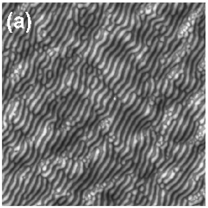
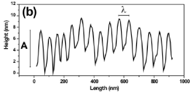
In contrast, the data typically obtained by SPM-techniques are displayed in Fig. 4. In this figure we show a typical ripple pattern obtained on a silicon surface by Ar+ ion bombardment at . In the cross-section we define two magnitudes that are usually studied, namely, the typical wavelength, , of the pattern and the amplitude of the ripple structures, . In particular, the analysis of the former is very interesting as different models predict different behaviors of , for instance, with the ion fluence. Thus, some models imply that increases with sputtering time, that is, that the pattern coarsens with time. Therefore, the eventual coarsening of is an object of study both experimentally and theoretically.
Ripple orientation
The dependence of the ripple orientation with is one of the most relevant morphological properties of ripple formation by IBS. There is a critical angle, , such that for the ripples are perpendicular to the beam direction while for the ripples run parallel to it. This fact, which was already observed on glass in the seminal work by Navez et al. Navez_1962 , is a classic behavior that was explained already by the theory proposed by Bradley and Harper Bradley_1988 . This behavior has been observed for many target materials such as glass, SiO2 Flamm_2001 and HOPG Habenicht_1999 . One of these examples is shown in Fig. 5 for the case of fused silica.
Ripple pattern: dependence on ion energy and type
-
•
Ion type— Ripple patterns have been produced by bombarding the target surface by different ions. The most frequently used species is Ar+ due to its low cost, inertness and relatively high mass. Among the noble gases, Kr+ and Xe+ have also been employed Ziberi_2005 . Also, ripple patterns have been induced using beams of Cs+ Maclaren_1992 , Ga+ Habenicht_2002 , O Liu_2001 ; Smirnov_1999 and N ions Smirnov_1999 . The two last cases imply, as explained before, that reactive sputtering effects can take place. Therefore, ripple formation by IBS is quite general a process virtually independent of the target materials and bombarding ions.
-
•
Ion energy— The study of the dependence of the pattern wavelength with the ion energy, , is quite interesting because it can be used to further check the consistency of the experimental erosion system with the assumptions of Sigmund’s theory Sigmund_1969 on which the different continuum models proposed so far are based.
Regarding the energy of the ions, the following distinction is usually made: (a) low-energy range, which is normally applied to ion energies smaller than 2-3 keV, and (b) medium-energy range, which is applied to quite a wide range of energies ranging from 10 keV up to 100 keV or even higher values. Despite the wide range of energies, most of the works addressing the influence of the energy on the ripple pattern report, a qualitatively similar behavior is found, namely, that the typical wavelength increases with energy following a power dependence of the type , where usually . Figure 6 shows two examples of ripple production on silicon targets with low-energy (a) and medium-energy (b) Ar+ ion beams. Clearly, the wavelength is quite different but the surface morphology is nonetheless similar.
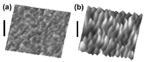
Figure 6: (a) AFM image of a Si surface bombarded by a 1 keV Ar+ ion beam at for ion dose of ions cm-2. (b) AFM image of a Si surface bombarded by a 40 keV Ar+ ion beam at for ion dose of ions cm-2. The vertical bars indicate 150 nm and 900 nm, respectively. This behavior has been found for Si targets irradiated at low-energy for different ion species: O Alkemade_2001 ; Vajo_1996 , Ar+ Ziberi_2005 , and, Kr+ Ziberi_2005 and Xe+ Ziberi_2006b , and also for sputtering experiments at medium-energy employing O ions Karmakar_2005 and Ar+ ions under ion beam scanning conditions Chini_2002 . Also, this dependence has been observed for SiO2 targets bombarded by low-energy Ar+ ions Umbach_2001 , for HOPG (bombarded by medium energy Ar+ ions) Habenicht_2001 and diamond (bombarded by medium energy Ga+ ions) Datta_2001 .
However, discrepancies arise when considering the values reported for the exponent . It should be noted that this study becomes especially difficult for low-energy IBS experiments in which, usually, the sampled energy range is quite narrow as recently pointed out in Ziberi_2005 . Furthermore, sometimes it is difficult to assess whether the experimental data follow a linear or, rather, a different power law behavior. Thus, for different targets irradiated by low-energies ions, values of in the 0.2-0.8 range have been reported Alkemade_2001 ; Umbach_2001 ; Vajo_1996 ; Ziberi_2005 .
For the medium ion energy experiments, the energy range sampled is usually wider due to the use of ion implanters. Therefore, the assessment of the quantitative dependence between and becomes more reliable. However, discrepancies still exist among the different values reported since values in the 0.45-1 range have been obtained Chini_2002 ; Habenicht_2001 ; Karmakar_2005 . Particularly interesting is the case of HOPG targets: when they were bombarded by Ar+ ions a linear relationship was found, but when the ion was Xe+ a power law behavior was observed with an exponent value 0.7 Habenicht_2001 .
Finally, quite a different behavior was found for Si targets bombarded by low energy Ar+ ions Brown_2005 . In this work was found to decrease with energy when the target surface was held at 717 ∘C, whereas no clear trend was observed for ripples produced at 657 ∘C. Also, an inverse relationship between and ion energy was reported by Chini et al. for ion beam sputtering of Si surfaces without beam scanning Chini_2002 . Suppression or application of the ion beam scanning could influence the actual temperature at the target surface. This fact would be in agreement with a similar inverse behavior observed for the experiments performed by Brown and Erlebacher at higher temperature Brown_2005 .
Ripple pattern evolution with time or ion fluence
The study of the ripple morphological evolution with irradiation time is usually done through the dynamics of two magnitudes, the ripple wavelength and the surface roughness. The former is related with the ripple lateral dimension and the latter with the vertical one (i.e., ripple amplitude). This study is quite important because eventual control of the pattern morphological properties would enable applications for technological purposes.
-
•
Ripple coarsening— The existence or not of ripple coarsening can be, as mentioned above, a touchstone for the continuum models. In fact, ripple coarsening is not predicted by the seminal BH theory Bradley_1988 or some of its non linear extensions Cuerno_1995 ; Facsko_2004 ; Makeev_1997 ; Makeev_2002 ; Vogel_2005 . In contrast, it is predicted by more recent theories Castro_2005 ; Munoz_2005 . Thus, the analysis of ripple coarsening becomes a relevant issue. Moreover, since there are systems that display and others that do not show ripple coarsening, it is necessary to assess experimentally the differences between them in order to elucidate which physical phenomena are behind the coarsening process. This coarsening process typically reflects in a power law dependence such as where is irradiation time (fluence) and is a coarsening exponent.
An example of coarsening behavior (see Fig. 7) shows two AFM images of a Si(100) surface irradiated by 40 keV Ar+ ions at 50∘ for different times together with typical surface cross-sections of the surface morphology for both cases. In all images, the ripples run along the perpendicular direction with respect to the projected ion beam direction (which runs along the horizontal axis of the top view AFM images). From the AFM images coarsening of the typical ripple wavelength is already evident. This is better appreciated in panel (c), together with the clear surface roughening that also implies a clear increase in the amplitude of the ripple morphology.
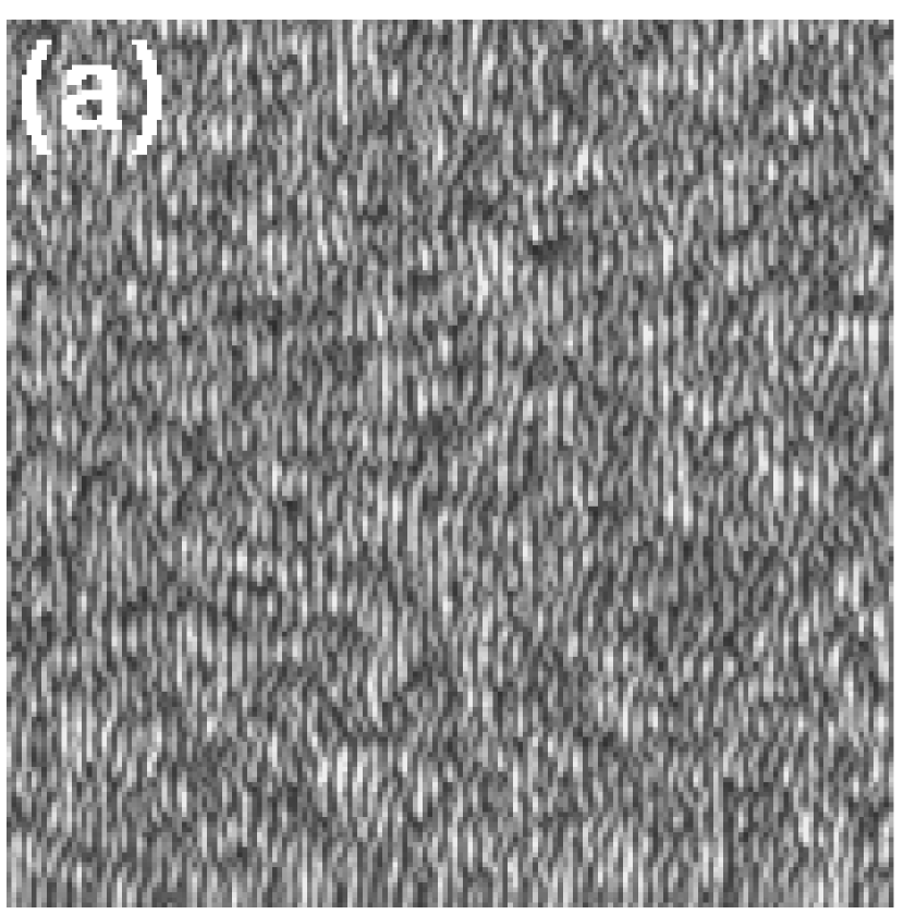
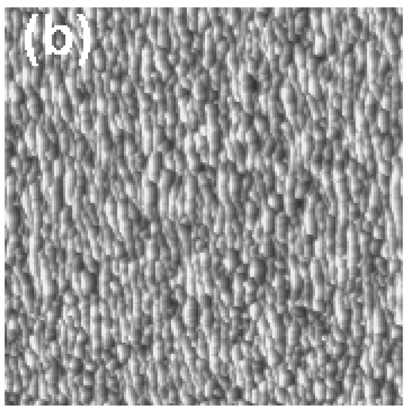
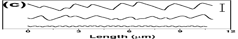
Figure 7: Top view AFM images of a Si(100) surface irradiated by 40 keV Ar+ ions at for different times (ion fluences): (a) , irradiation time 2 h ( ions cm-2) ; (b) , irradiation time 16 h ( ions cm-2). (c) Typical surface profiles taken along the projection of the ion beam of the samples irradiated for 2 h (bottom profile), 8 h (ion fluence of ions cm-2; middle profile) and 16 h (top profile). For the case of Si targets, we find ripple coarsening for low-energy ion irradiation experiments with 0.5 keV Ar+ ions impinging at 60∘ Brown_2005b . Moreover, this coarsening process has been observed for a relatively wide substrate temperature range, from 600 ∘C up to 748 ∘ C Brown_2005 . Also, a coarsening process was observed for 1.5 keV Ar+ ions impinging at 45∘ and room temperature Kulriya_2006 and 1 keV O ions impinging at 52∘ Liu_2001 for both high and low ion fluxes.
In contrast, coarsening was not observed for irradiation experiments performed at 582∘C and at 67.5∘ with 0.75 keV Ar+ ions Erlebacher_1999 . This was also the case for experiments done by bombarding the Si surface at with a 1.2 keV Ar+ ion beam. The same behavior was found when the ion species were Xe+ or Kr+ Ziberi_2005 .
For the medium-energy ion range, ripple coarsening has been reported for Si surfaces bombarded at by 20 keV and 40 keV Xe+ ions where target temperatures were maintained between 100-300 K Carter_1996 . Similarly, it has been observed for Si targets irradiated either by 60 keV Ar+ ions at Datta_2004 or by 30 keV Ga+ ions at Habenicht_2002 .
In other materials, ripple coarsening has been observed for HOPG and diamond surfaces. In the first case, the irradiation process was performed by 5 keV Xe+ ions at and Habenicht_1999 whereas in the last case Ga+ ions impinged at with energies of 50 keV and 10 keV Datta_2001 . Also, ripple coarsening has been reported for fused silica bombarded by an 0.8 keV Ar+ ion beam at Flamm_2001 and for glass targets irradiated by 0.8 keV Ar+ ions, which were generated in a defocused electron cyclotron resonance plasma, with an angle of incidence of Toma_2005 . Finally, ripple coarsening was also observed for InP targets irradiated at by 0.5 keV Ar+ ions Demanet_1995 but not for GaAs surfaces bombarded at by 10.5 keV O ions Karen_1991 .
With regard to the value of the exponent different values have been reported. Thus, on silicon targets a value of 0.5 for irradiation at 30 keV has been reported Habenicht_2002 . Also for high energies, 60 keV, two regimes with values and were observed. In contrast, for low-energy irradiation experiments an exponential dependence, rather than a power-law, was found for a relatively wide range of substrate temperatures Brown_2005 . When 0.8 keV Ar+ ions were employed to irradiate fused silica Flamm_2001 and glass surfaces Toma_2005 coarsening exponents of 0.15 and 0.95 have been found, respectively.
Finally, only for 60 keV Ar+ ion irradiation at of GaAs surfaces, a disordered dot morphology has been reported previous to, and later coexisting with, the ripple morphology Datta_2002 . For long sputtering times (i.e., ion fluences of ions cm-2) only the ripple morphology remained, without any nanodot structure superimposed.
-
•
Surface roughening— The study of the surface roughness, —defined as the mean square deviation of the local height with respect to its mean value— of the patterns can be very useful for both technological (e.g. developing metal surfaces for SERS applications) and fundamental purposes. In principle, should be proportional to the ripple amplitude (i.e., the peak to valley height difference), , in case the patterns were perfectly periodic. However, in real patterns there are height fluctuations among ripples that imply that and are not completely equivalent. Although most part of the studies deal with , some of them analyze rather than .
The most frequently observed behavior is that initially increases steeply (usually increasing exponentially with ion fluence or sputtering time) to either saturate or grow at a slower pace, usually following a power law dependence such as . In the latter case, it is interesting to measure the value of since it can be contrasted with predictions from theoretical models.
For the first case, i.e., exponential increase followed by saturation, we can mention experiments on Si surfaces irradiated by low-energy Ar+ ions Erlebacher_1999 , Ziberi_2005 .
The second case, i.e., sharp increase followed by power law behavior, has also been observed in many systems: Si targets bombarded by medium-energy Ar+ ions Datta_2004 ; Karmakar_2005 and also for HOPG surfaces bombarded under similar conditions Habenicht_2001 . For Si targets irradiated by 60 keV Ar+ ions an initial value of was reported, although this relatively high value could be compatible with an exponential increase, whereas for longer times was found Datta_2004 . In addition, for 16.7 keV O ions was observed after the initial sharp increase of Karmakar_2005 . Also, for HOPG surfaces irradiated by 5 keV Xe+ ions a value compatible with the Kardar-Parisi-Zhang Kardar_1986 universality class was reported Habenicht_1999 ; Habenicht_2001 .
Finally, there are works where only power-law behaviors were reported. Most of these systems studied present a value such that Carter_1996 ; Datta_2004 ; Flamm_2001 ; Toma_2005 (in the second case, for low ion flux conditions). These behaviors could be due to partial analysis of the initial exponential increase that, when analyzed in a limited temporal range, can be analyzed in terms of a power law dependence with an exponent as remarked.
-
•
Shadowing effects— An important issue that should be taken into account for studying ripple evolution is geometrical shadowing. These effects appear for long sputtering times and when relatively large values are employed. The important role of shadowing effects was highlighted in Carter_1996 ; subsequently, Carter gave a simple estimation of the conditions under which these effects begin to operate Carter_1999 . In particular, he proposed that shadowing operate for ripples with an amplitude (here taken as proportional to ) to wavelength ratio such that
(2) In equation (2) as increases (i.e., approaching grazing incidence) the right hand side making shadowing effects more likely to appear. These effects have been considered recently for Si irradiation by 60 keV Ar+ ions at Datta_2004 ; Datta_2005 . According to (2), shadowing effects should appear when , which occurs after 800 s of irradiation under the sputtering conditions described in Datta_2004 . Interestingly, this value is very close to the threshold time for which ripple coarsening begins to be observed. Thus, shadowing effects can influence largely the ripple dynamics. This fact can be important because usually shadowing is not incorporated into continuum models. Moreover, the latter are usually derived under a small slope approximation and the abrupt morphologies generated when shadowing processes appear cannot be described under such approximation. A remarkable exception is the continuum equation proposed in Chen_2005 that seems to correctly describe steep surface features.
Ripple pattern dependence on target temperature
The study of the pattern evolution with target temperature can contribute to further increase our knowledge of the main physical mechanisms governing the IBS pattern formation. In particular, temperature can affect the surface diffusivity, which can lead to changes in the morphology of the pattern. However, studies are scarce due, probably, to their experimental complexity. For low-energy ions there are two reports on silicon surfaces irradiated by Ar+. In the first one, in which 0.75 keV Ar+ ions impinged at onto the surface Chason_2001 ; Erlebacher_1999 , coarsened with the target temperature in the 460-600∘ C range following an Arrhenius law Makeev_2002
| (3) |
These data are shown in Fig. 8. The value of obtained at the lowest temperature was measured by AFM because it was out of range of the light spectroscopy measurements. This analysis led to a value for the activation energy, ( eV) for surface mass transport on ion-bombarded Si(001).
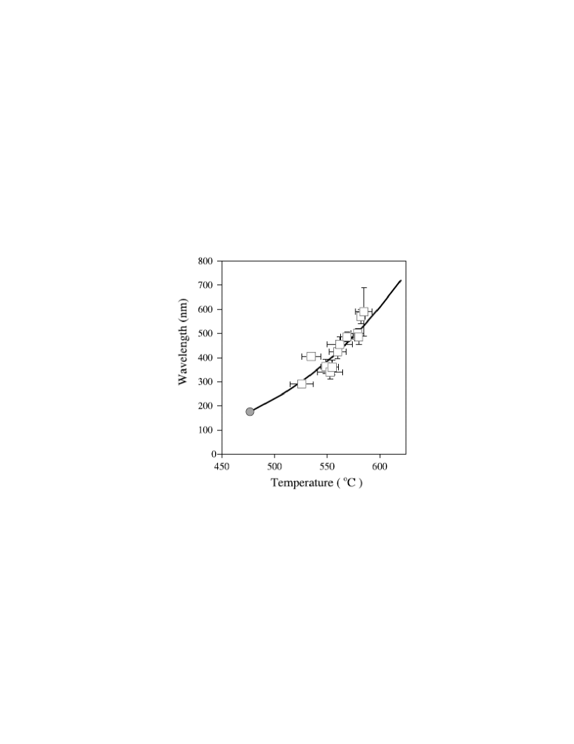
/p2330) with permission
.
The same behavior was found for Si(111) irradiated at 60∘ by 0.5 keV Ar+ ions in the 500-750∘ C range Brown_2005 . This study led to eV. Similarly, for SiO2 targets irradiated by 0.5-2 keV Ar+ ions an Arrhenius behavior was observed for C Umbach_2001 .
Finally, there are two reports on the variation of the pattern with target temperature for medium-energy IBS experiments. In the first one, HOPG surfaces were irradiated by 5 keV Xe+ ions in the 573-773∘ C range Habenicht_2001 . For this system the ripple wavelength followed also the Arrhenius law giving a value of eV. The second experiment was on bombardment of GaAs targets by 17.5 keV Cs+ ions at Maclaren_1992 , in which the ripple wavelength was analyzed in the C range. The data obtained have been later analyzed in Malherbe_2003 . For , the behavior was well described by Eq. (3) with an activation energy for surface self-diffusion of eV. For lower temperatures, a slight decrease of was observed following a law. However, within error bars, these experimental data are also compatible with a temperature independent behavior, in agreement with models for effective surface diffusion effects of erosive origin Makeev_1997 ; Makeev_2002 . In any case, the present experiment Maclaren_1992 ; Malherbe_2003 provides a clear example of the existence of different temperature regimes for ripple formation under IBS.
In contrast, Carter and Vishnyakov did not find any change of with temperature in the sampled 100-300 K range when Si targets were irradiated by 10-40 keV Carter_1996 . These findings are consistent with the existing theories since for relatively low temperatures ion-induced surface diffusion processes, which not depend on the target temperature, dominate over thermally activated ones Makeev_1997 .
Ripple pattern dependence on ion flux
The ripple pattern morphology, in particular its wavelength, can depend also on the ion flux, , i.e., the number of incoming ions per area and time units.
Among the scarce studies of this behavior, most of them did not find any change of the ripple wavelength with ion flux. This was the case for Si surfaces bombarded by either 1.5 keV O ions at Vajo_1996 or by low-energy Ar+ ions at different ion fluences Brown_2005 or by 2 keV Xe+ ions at Ziberi_2006b . In addition, the same behavior was found for fused silica targets irradiated at at different angles by a low-energy Ar+ ion beam Flamm_2001 . Also, no change of with the ion flux was obtained for diamond surfaces irradiated by 50 keV Ga+ FIB at Datta_2001 . All these studies were done at room temperature, except for the one on fused silica that was performed at 12∘ C.
In contrast, for Si surfaces bombarded by 0.75 keV Ar+ ions at 67.5 degrees to normal in the 500-600∘ C range Erlebacher_1999 , was found to decrease with , as . Also, a decrease of the ripple wavelength with ion flux was reported for Si surfaces bombarded at room temperature by 1 keV O ions at , although in this case the quantitative dependence was not addressed Liu_2001 .
Ripple pattern order
The size of ordered ripple domains is another essential property of these patterns for potential technological applications. However, it is somehow difficult to assess. In principle, there may be several methods to evaluate it. A first one is based in the data obtained by AFM. From these data, it is straightforward to obtain the Power Spectral Density (PSD) of the surface morphology, . The PSD is defined as , where is the Fourier transform of with being the space average of the height and . This PSD curve usually presents a peak denoting the existence of a characteristic mode whose associated length scale is identified with the ripple wavelength . It has been proposed that the pattern lateral correlation length, , which gives an estimation of the average size of the ordered domains, can be obtained from the full width at half maximum of the PSD peak Zhao_2001 . This method was employed by Ziberi et al. Ziberi_2005 for estimating the range of order of ripple patterns produced by 1.2 keV Ar+, Kr+ and Xe+ ions at on silicon surfaces. Although in these experiments coarsening was not observed, (thus was constant for all the ion fluences), in all cases was observed to increase with the ion fluence (especially, for the largest ion fluences was found). In this work, the authors also studied the change of with the ion energy for the three different ions employed. Whereas for Xe+ and Kr+ ions and were found to increase in the same way with ion energy, for the case of Ar+ ions a maximum for the ratio was observed for an ion energy of 1.2 keV. It should be noted, that for the largest energy employed in all cases, 2 keV, , irrespectively of the ion species.
The previous method for assessing the pattern order degree has the disadvantage of the local character of SPM techniques. However, there is another method, based on grazing incidence diffraction (GID) or small angle scattering (GISAXS) synchrotron techniques, that provides better sampling statistics. However, to our knowledge, there is no published work using this technique for such purposes on amorphous materials where it has been used ripple crystallinity assessment Hazra_2004 .
Ripple propagation
The transversal collective motion of ripples has only been studied in two works by simultaneous real time monitoring of the ion-induced ripple morphology by SEM. In the first one Habenicht_2002 a Si surface was irradiated by 30 keV Ga+ ions and = 30∘, it was found that ripples initially propagated along the ion beam projection direction with a velocity of = 0.33 nm s-1 to slow down later on as they coarsened. In the second case, in which glass surfaces were irradiated by 30 keV Ga+ ions Alkemade_2006 , ripples also propagated along the projection of the ion beam direction. In this case,the ripple evolution was shown in real time. Moreover, ripples did not initiate the propagation until most of them were completely formed, to finally reach an uniform propagation velocity.
Nanodot patterning in amorphous/amorphizable materials
Dot IBS nanopatterns are produced when the anisotropy caused by the oblique incidence of the ion beam is suppressed. Basically, there are two ways to eliminate this anisotropy: (a) by IBS under normal incidence, which is the most frequently employed technique Facsko_1999 ; Gago_2001 ; (b) by IBS under oblique incidence but with simultaneous rotation of the target Frost_2000 . More recently, nanodot patterns have been produced on Ge surfaces by a 2 keV Xe+ ion beam impinging on the Ge surface at Ziberi_2006 , possibly related with the role of the critical angle mentioned at the beginning of Sec. 3.1.
These patterns are usually characterized by a highly uniform dot size distribution and short-range in-plane ordering. These two properties make them very interesting for potential technological applications. Although the first report on the production of such IBS nanopatterns Facsko_1999 is relatively recent, dating from 1999, many groups are investigating the mechanisms leading to their formation. Thus, up to now, these patterns have been produced in different materials: GaSb Bobek_2003 ; Facsko_1999 ; Frost_2003 ; Xu_2004 , InP Frost_2000 , InAs Frost_2004b , InSb Facsko_2001 , Si Gago_2001 ; Gago_2002 ; Ziberi_2005b , and Ge Ziberi_2006 .
As occurred for the ripple patterns, the formation of the dot patterns under different experimental conditions and for a relatively wide range of materials suggests that this process does not depend on the specific ion-target interactions.
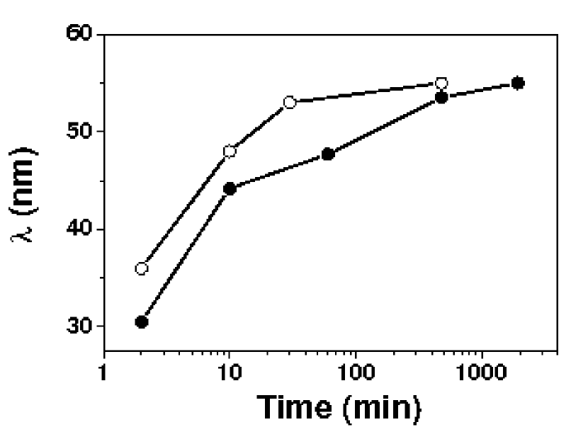
Another important issue regarding the target material is its crystallinity. Thus, it has been proved that, for GaSb targets, IBS nanodot patterns can be produced both on crystalline Facsko_1999 and amorphous surfaces Facsko_2002 . In addition, these patterns have been produced by IBS on both Si(100) and Si(111) surfaces Gago_2006 . In this work, it was found that, although the surface crystallinity does not affect the pattern formation, it can affect to some extent the pattern dynamics. In particular, it was observed that Si(111) surfaces have a faster dynamics in terms of pattern coarsening (see Fig. 9) and ordering than Si(100) surfaces. Again, the fact that the surface crystallinity does not determine the formation of the pattern is compatible with Sigmund’s theory Sigmund_1969 for which the surface is considered as amorphous, either originally or as induced by the ion beam action.
In the following, we will review the main experimental findings on the properties of these patterns depending on the different experimental parameters. One of the most studied issues is the variation with physical parameters of the basic pattern length scale, , which now corresponds to the average dot-to-dot distance, usually proportional to the dot size. It is worth noting that the interest in these studies on the dot shape and size lies in the required control of these parameters, particularly the dot size, for developing technological applications.
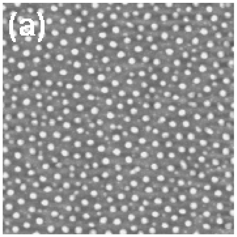
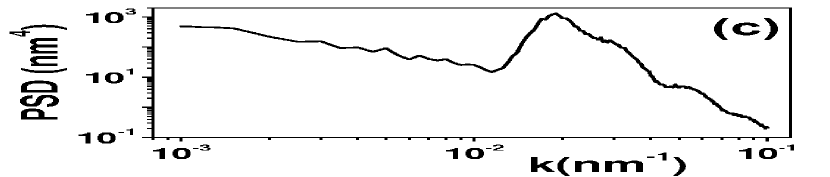
It should be noted that, whereas the dot size is usually affected by the AFM tip (AFM being the routine technique for characterizing the surface morphology), the dot-to-dot distance is not usually affected by tip convolution effects Frost_2001 . The pattern wavelength is usually determined from the radially-averaged PSD of AFM images as is shown in Fig. 10. In panel (a) of this figure we display a typical AFM image of a nanodot pattern induced onto a Si(100) surface. Panel (c) shows the radially-averaged PSD function corresponding to this image, in which we can observe a dominant peak corresponding to the basic wavelength . At higher values we can detect other minor peaks or shoulders indicating the high lateral ordering and size homogeneity of dots Ziberi_2006c . Conversely, panel (c) also illustrates the power-law behavior of the at small , which signals height disorder between dots at long distances. This behavior is very frequently found for this type of experiments.
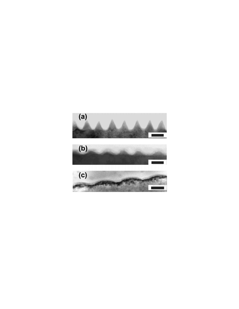
Similarly to the case of ripples, TEM analysis can provide us useful information regarding the morphology and structure of the dot patterns. Thus, different dot morphologies obtained by TEM are presented in Fig. 11. In (a) we observe the conical morphology of crystalline GaSb dots produced under normal irradiation and target rotation Frost_2004c . In contrast, in (b) we observe GaSb dots with a sinusoidal shape obtained under irradiation at and target rotation. In these cases, the amorphous layer thickness was nm Frost_2004c . Finally, in (c) we observe Si nanodots produced under normal irradiation without target rotation displaying, rather, a lenticular shape with an amorphous layer thickness of nm Gago_2001 .
Nanodot pattern dependence on ion energy and type
-
•
Ion type— To date, all the experiments in which nanodot patterns have been reported are done with low-energy Ar+ ion beams, except for one work in which Ne+, Kr+ and Xe+ ion beams were also employed Ziberi_2006c . In this work oblique ion beam incidence and simultaneous target rotation were employed. Although some characteristics of the pattern differed, the authors concluded that there was almost no difference in the morphological evolution of the mean size of dots when using different ions. In contrast to the experimental findings of the same group on ripple formation, the use of Ne+ ions did lead to the production of nanodot patterns with an experimental behavior similar to that observed when Ar+ ions were employed. Recently, experiments have been performed using 1 keV O ions Tan_2006 . However, in this work a sort of nanodot chains was produced that seem more similar to nanoripples with a superimposed nanodot morphology.
-
•
Ion energy— Regarding the energy range used in the nanodot experiments, there is a marked difference with respect to the studies realized on nanoripple IBS production (see above). Namely, for nanodot experiments only low-energy ions have been used, with keV. As remarked earlier in Sec. 3.1, working in this energy range can lead to relatively large errors in the determination of the power-law dependence , especially in the value of Frost_2003 . However, this was not the case for the study by Facsko et al. for IBS nanodot patterns on GaSb since they sampled 15 energy values within this range Facsko_2001 . They obtained a value of . In the same study the authors estimated, a similar value for InSb surfaces from three experimental data points.
In Fig. 12 we present our results on GaSb surfaces irradiated at different ion energies. Clearly, the dot size coarsens with ion energy. In fact, our experimental data are consistent with an exponent of as in the case of Facsko and coworkers Facsko_2001 . Also we must note the evident surface roughening with ion energy given that the vertical scale is the same in all three AFM images.
Another experimental study was done by the group of Frost and coworkers for Si surfaces with Ne+, Ar+, Kr+ and Xe+ oblique ion beams onto rotating Si targets Ziberi_2006c . In all cases, they found an increase of with ion energy. Unfortunately, they did not estimate the value of . However, from a visual inspection of Fig. 6 of Ziberi_2006c it is clear than .
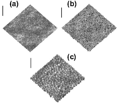
Figure 12: (a) AFM images of a GaSb substrate irradiated with Ar+ ions under normal incidence with an approximate fluence of ions cm-2 at: (a) 0.3 keV; (b) 0.7 keV; (c) 1.2 keV. The vertical bars correspond to 200 nm. Note the surface roughening and dot-size coarsening with increasing ion energy.
Nanodot pattern evolution with sputtering time or ion fluence
The study of the influence of sputtering time (i.e., ion fluence) on the pattern morphology has attracted the interest of the researchers already since the seminal work by the group of Facsko and coworkers Facsko_1999 . As occurred for the ripple morphologies, two main dynamics are studied: that of the pattern wavelength and the evolution of surface roughness.
-
•
Dot nanopattern coarsening— Basically, the same behavior is observed for many of the various experimental systems: initially, increases to saturate afterwards. However, the dynamics of this process is quite different depending on the target material and ion current density. Thus, for GaSb surfaces Bobek_2003 ; Xu_2004 and InP Frost_2000 ; Frost_2003 the saturation regime is attained for ion dose close to ions cm-2. It should be noted that this saturation was attained for an ion dose of ions cm-2 when InP targets were irradiated under normal incidence by Ar+ ions without rotation, but with a flux six times smaller Tan_2006b than that employed in Frost_2000 . For Si surfaces saturation takes place for a considerably larger ion dose, at ions cm-2 Gago_2006 . In another study where the Si surface was intentionally seeded with molybdenum, can be estimated to saturate at an ion dose of Ozaydin_2005 . The different dynamics of GaSb and Si surfaces under normal incidence Ar+ irradiation and rotating InP targets under oblique Ar+ bombardment is shown in Fig. 13, where results obtained on these systems are displayed.
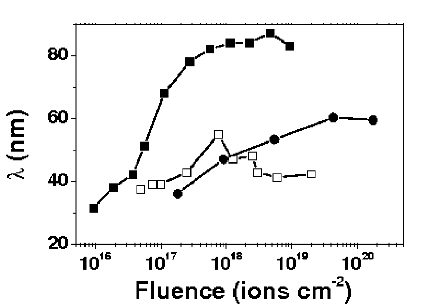
Figure 13: Dependence of the characteristic pattern wavelength with ion fluence for GaSb, mA cm-2 (), InP at mA cm-2 () and Si at mA cm-2 () surfaces. The data for GaSb and InP have been adapted from Bobek_2003 and Frost_2000 , respectively. Measurement of the exponent in the power law dependence before saturation has been done for four systems: (a) for Si surfaces irradiated under normal incidence by 1.2 keV Ar+ ions with mA cm-2 Gago et al. found Gago_2001 . (b) For GaSb targets sputtered by 0.5 keV Ar+ ions under normal incidence with mA cm-2 Xu et al. reported Xu_2004 . (c) For rotating InP targets irradiated by oblique 0.5 keV Ar+ ions with mA cm-2, Frost et al. reported a value of Frost_2000 ; Frost_2003 . (d) For InP targets irradiated under normal incidence by 1 keV Ar+ ions with mA cm-2 , Tan et al. reported a value of Tan_2006b .
In addition, for Si surfaces irradiated by 0.5 keV Ar+ ions Ludwig et al. did observe a coarsening process with sputtering time but they did not estimate the value of the coarsening exponent Ludwig_2002 . However, they did not observe the saturation regime up to ion doses of , which agrees with other experimental reports on Si surfaces. Besides, the authors did find that the coarsening exponent value increased with the ion energy in the 100-200 eV range. However, the opposite behavior, i.e., absence of coarsening, was observed by the group of Frost for rotating Si targets irradiated by oblique beams of Ne+, Ar+, Kr+ and Xe+ ions Ziberi_2005b ; Ziberi_2006c .
-
•
Surface roughening— The surface roughness gives us a measure of the nanodot height as well as of the height fluctuations among dots. For GaSb surfaces Bobek_2003 , initially increases rapidly with sputtering time to reach later a maximum value. In this first region Xu and Teichert obtained Xu_2004 . Again, this high value could be an indication that the surface roughness increases exponentially rather than follow a power law. For longer times the surface roughness decreases to attain a saturation value.
For the case of InP targets irradiated under normal incidence conditions a first regime for which was reported Tan_2006b . This regime led to another one in which , also roughly compatible with roughness saturation. In contrast, for rotating InP targets Frost_2000 , the surface roughness increases for the whole temporal range that was sampled. A first value was measured, once more possibly compatible with an exponential time dependence, while for longer times was obtained.
For Si targets, both fixed and rotating, a similar behavior of the roughness has been reported, namely a sharp initial increase followed by saturation Gago_2001 ; Ozaydin_2005 ; Ziberi_2006c . In the latter study, the behavior observed for Ar+, Kr+ and Xe+ ions was found to be consistent with an initial regime during which the roughness increased exponentially.
The main findings of the above works are displayed in Fig. 14 where we plot the evolution of with sputtering time for the GaSb, InP and Si systems. In this plot we have represented the -axis in logarithmic scale in order to display the three systems in a single graph, which have different dynamics. It can be appreciated that, although the temporal evolution is different for each system, there is always a sharp initial increase of the roughness before reaching either a stationary value or a regime with a slower growth. In the inset we display the same plot only for the initial stages of the sputtering process (i.e., s); now the -axis is the one in logarithmic scale so that for all three systems the initial roughness seems to increase exponentially with time as the straight lines suggest in the plot .
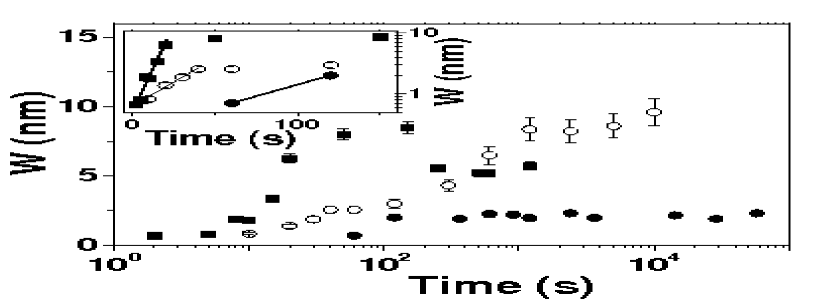
Figure 14: Surface roughness vs sputtering time for IBS dot patterning of GaSb irradiated under normal incidence (), InP bombarded under oblique incidence and simultaneous target rotation (o) and Si irradiated under normal incidence (). Note that the temporal axis is in logarithmic scale. Inset: same graph but restricted to short sputtering times, i.e., s. Note that now the -axis is in logarithmic scale. The solid straight lines are guides to eye to indicate the exponential dependence of the initial roughness increase for the GaSb, InP and Si systems, respectively. Finally, we have also studied Gago_2001 , how the surface roughness changes with the substrate temperature for Si targets irradiated under normal incidence. We observed that , which was constant for temperatures up to 400 K, decreased to reach a saturation value at 550 K where the pattern vanished Gago_2006b .
Nanodot pattern dependence on target temperature
To the best of our knowledge, there are four studies on the dependence of the pattern morphology on the target temperature, each one on a different material. Thus, we will describe separately the main findings of these studies.
-
1.
GaSb surfaces irradiated under normal incidence by 0.5 keV Ar+ ions Facsko_2001 : for this system the pattern wavelength did not change with target temperature between C and C. This behavior was interpreted as a confirmation that the main relevant smoothing process is nonthermal under these experimental conditions; the main relaxation process is, rather, due to ion-induced effects Makeev_1997 .
-
2.
Rotating InP surfaces irradiated by 0.5 keV Ar+ ions impinging at 30∘ Frost_2003 : in this case, quite a striking complex behavior was found since pattern symmetry changed in the temperature range between 268 K and 335 K from short-range hexagonal to square patterns symmetry. In addition, the characteristic wavelength increased with temperature Frost_2004b . This behavior is shown in Fig. 15.
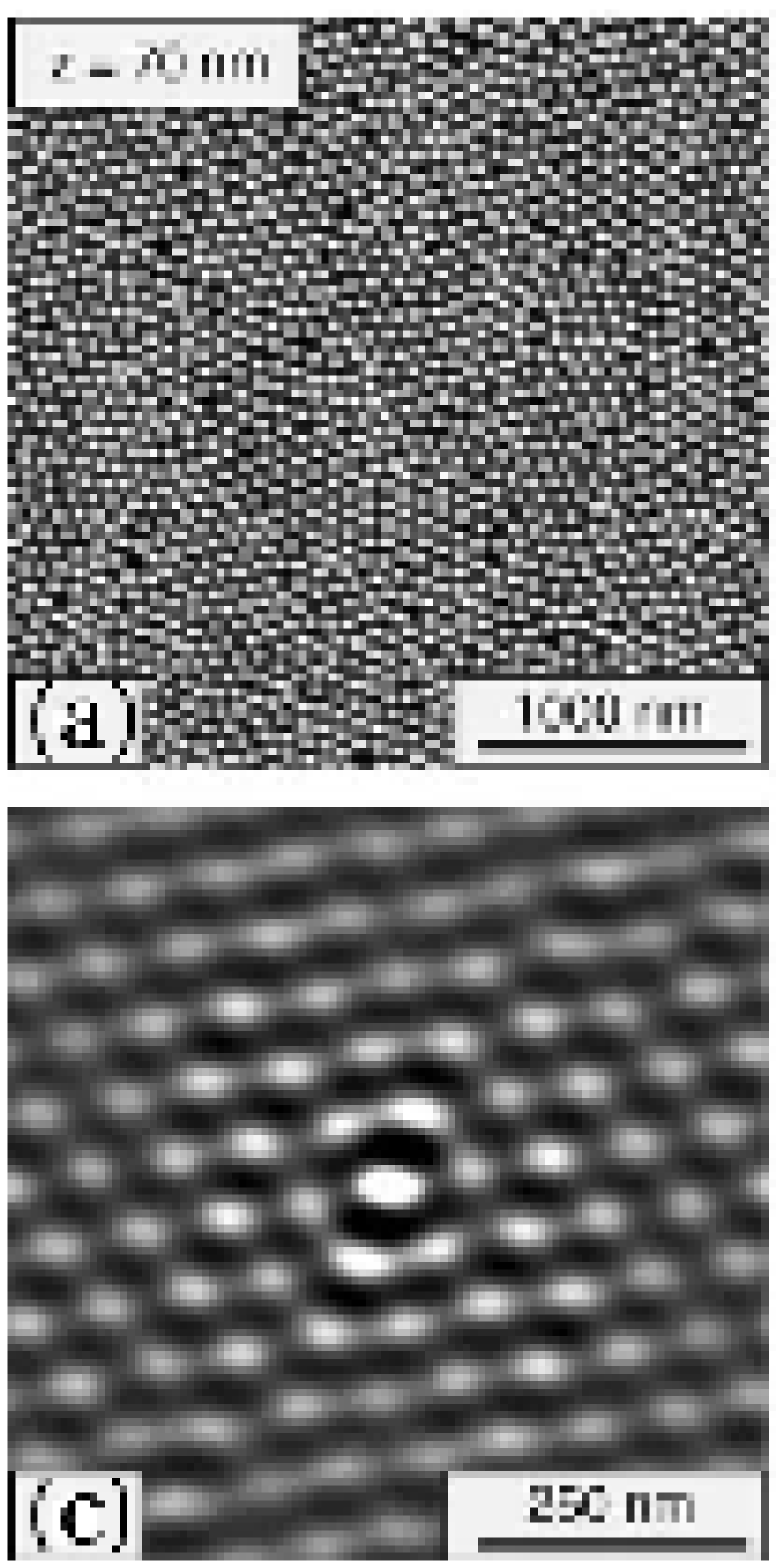
Figure 15: AFM images of a rotating InP target irradiated at by 0.5 keV Ar+ at A cm-2 at different target temperatures: (a) 268 K, (b) 335 K. The corresponding two-dimensional autocorrelation functions are displayed in (c) and (d), respectively. Figure reprinted from Frost_2004b with permission. -
3.
For Si targets irradiated by 1.2 keV Ar+ ions Gago_2006b was observed, by both AFM and GISAXS, the nanopattern wavelength to be a constant up to 425 K, and then to decrease in the 425-525 K range. For higher temperatures the pattern vanished and the surface became featureless. This behavior is not explained by any of the existing theories on IBS nanostructuring. In Fig. 16 we display AFM images of IBS induced dot patterns at 300 K (a) and 425 K (b) showing qualitatively how both and the dot size become smaller with increasing substrate temperature. This shrinking process becomes evident in panels (c) and (d) in which we show the PSD and GID curves measured on both patterns, respectively. In both cases, the main peak shifts to higher and values, i.e., the characteristic length scale diminishes as substrate temperature increases Gago_2006b .
Figure 16: nm2AFM images of a Si(100) substrate irradiated at normal incidence by 1.2 keV Ar+ at different target temperatures: (a) 300 K, (b) 425 K. The vertical bars indicate 25 nm. PSD (c) and GID (d) curves for the patterns produced at 300 K () and 425 K (o). The vertical solid and dashed lines indicate the (PSD) and / (GID) values for the 300 K and 425 K systems, respectively. -
4.
Fixed InP surfaces irradiated under normal incidence Tan_2006b by 1 keV Ar+ ion beam, which was scanned over the target surface, at mA cm-2 with a fluence of ions cm-2 at three temperatures, namely -110∘ C, 23∘ C and 36∘ C. Under these conditions the pattern was only obtained at . In parallel, surface roughness increased markedly with temperature from 0.5 nm up to 76.8 nm.
In addition, there is one study Fan_2005 where it is found that for low ion fluxes the dot size changes with increasing temperature according with the existence of Ehrlich-Schwoebel energy barriers Ehrlich_1966 ; Schwoebel_1966 whereas for high ion fluxes the dot size decreases with temperature. However, Si dots seem to arrange differently from other IBS nanodot structures induced on Si surfaces, specifically a clear pattern can not be visualized.
Nanodot pattern dependence on ion flux
For GaSb Facsko_2001 ; Frost_2003 and InP Frost_2003 surfaces it was found that the pattern wavelength was independent of the ion current density or ion flux for the different ranges sampled, namely cm-2 s-1 and cm-2 s-1, respectively. For fixed InP targets irradiated at normal incidence by 1 keV Ar+ ions at fixed fluence and 23∘, Tan and Wee Tan_2006b found that at low ion fluxes there was not any dot pattern but it appeared at jion = 0.0174 mA cm-2. The pattern in-plane hexagonal order increased when ion flux was increased up to jion = 0.0233 mA cm-2. In another study, where dot structures did not form a clear pattern, it was proposed that for ion fluxes below 220 A cm-2 Ehrlich-Schwoebel energy barriers Ehrlich_1966 ; Schwoebel_1966 dominate while for higher flux values the dot size decreased as Fan_2005 .
In-plane order of nanodot pattern
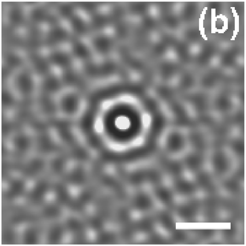
The nanodot patterns usually present short-range hexagonal in-plane order. The analysis usually employed for assessing their degree of order is made through the two-dimensional auto-correlation function of the AFM images
| (4) |
which is a measure of how well a structure matches a space-shifted version of itself Zhao_2001 . An example is shown in Fig. 10 where an AFM image of the dot pattern is displayed in panel (a) together with its corresponding 2-D auto-correlation (panel b). Here, six bright spots are clearly observed indicating the short-range hexagonal ordering of the dot pattern.
When the symmetry of the pattern is large, it can be also assessed through the two-dimensional Fourier Transform (FFT) of the AFM images Ziberi_2006 , although this is not the most common case, as IBS patterns usually give ringed FFTs Ziberi_2006 .
Besides the symmetry of the pattern, a further issue is to quantify its degree of order in the pattern. As mentioned for the ripple patterns, two main approaches exist: (a) through size of the mean peak of the PSD of AFM images, and (b) using synchrotron techniques such as GISAXS and GID.
Based on PSD data, Bobek and coworkers observed that the range of order of the nanopattern for GaSb surfaces increased appreciably after 100-200 s of Ar+ ion irradiation Bobek_2003 . Also with this type of analysis the group of Frost found that the range of in-plane order decreased with increasing temperature, in the 268-335 K range, for rotating InP surfaces sputtered at by 0.5 keV Ar+ ions Frost_2004b .
Two studies have been performed for Si surfaces. For rotating Si substrates bombarded at by either 0.5 keV Ar+ ions, by 1 keV Kr+ ions or by 1 keV Xe+ ions Ziberi_2006c ; Ziberi and coworkers obtained that the lateral correlation length, , increased with sputtering time up to a value close to 170 nm, in the window sampled, when Ar+ ions were employed. In contrast, for both Kr+ and Xe+, saturated at nm, and nm, respectively. Saturation took place earlier for Xe+. Moreover, the change of with ion energy depended on the ion species. Thus, for Kr+ and Xe+ the order increased with ion energy until the normalized correlation length, , saturated for 1 keV. In contrast, for Ar+ ions had a maximum value at 0.5 keV.
The second system consists of a fixed Si target bombarded at normal incidence by 1.2 keV Ar+ ions. In this work, we used both AFM and synchrotron techniques to study the pattern dynamics in terms of coarsening and ordering as functions of sputtering time. In Fig. 17 we display the data obtained on Si by our group Gago_2006 and by the group of Frost Ziberi_2006c in terms of the normalized ordered domain size (i.e, the ratio of the lateral correlation length to the pattern wavelength) versus ion dose. For the rotating Si target the order seems to increase with ion dose irrespective of the ion species, although saturation is observed for 1 keV Kr+ ions but not for 0.5 keV Ar+. In principle, it appears that the order of the pattern is larger for the rotating substrate configuration than for the fixed configuration when Ar+ ions are employed. However, it should be noted that for 1 keV Ar+ ions the order for the rotating configuration dropped to less than half that obtained for 0.5 keV Ar+ ions.
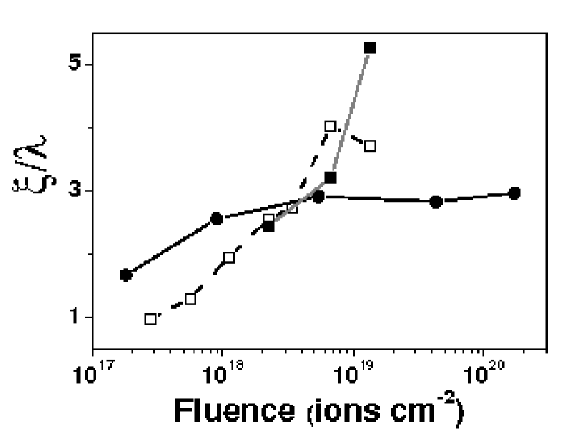
Regarding the quantification of the range of order in the pattern, SPM-based techniques pose a problem due to their locality. These surface characterization techniques sample a relative small area of the surface and lack enough statistics to a certain extent. Thus, in a recent work Gago_2006 , we have used AFM and synchrotron based techniques (namely, GISAXS and GID) to quantify the ordering of the same IBS patterns. The corresponding results for the normalized ordered domain size are presented in Fig. 18. Clearly, AFM data saturate at a value very close to 3 while GID data roughly increase monotonously in the sampled temporal window up to a value close to 10. This difference is due to the improved sampling statistics of GID with respect to AFM Gago_2006 . Thus, although AFM is a well suited technique for routine characterization of IBS nanopatterns, GID and GISAXS can provide us with more reliable quantitative data.
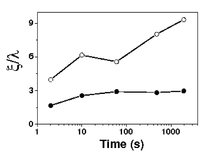
Nanohole or nanopit patterning
In principle, hole nanopatterns can also be induced by IBS. The fact that nanodots or nanoholes are produced on the target surface depends only on the anisotropies of the collision cascades Kahng_2001 . After the ion sputtering theory by Sigmund Sigmund_1969 this shape depends only, for a given target material and ion species, on the ion energy. However, despite such a theoretical prediction, there is not clear evidence, up to now, of hole or pit pattern production by IBS. Two main pit-structures have been produced by IBS: the so-called cellular structures Chen_1997 ; Chey_1995 ; Frost_2004c ; Hofer_2004 and hole structures on semiconductor heterostructures Lau_2003 . The former look like network of hole-like structures, with a relatively wide distribution of hole sizes, resembling those obtained in plasma etching of silicon Zhao_1999 . In contrast, those induced on semiconductor heterostructures display a more homogeneous hole size distribution with typical hole diameter of nm and hole spacing of nm.
Recently, we have achieved the production of nano-hole patterns by IBS on silicon surfaces. These patterns display a characteristic wavelength similar to that obtained on the standard IBS experiments on dot pattern production. As an example we present in Fig. 19a a typical AFM image of a nanohole IBS pattern. The hole structures are 2-3 nm deep and have a lateral size in the 30-40 nm range. It should be noted that both the hole depth and lateral size can be underestimated because of tip convolution effects. The inset of Fig. 19a displays the auto-correlation of an AFM image taken over an area of nm2. Although there is some distortion, the short-range hexagonal order is clear. Finally, in panel (b) the radially averaged PSD function of image (a) is presented. Similarly to the results obtained above for nanodot patterns, the PSD presents a clear peak that is associated with the characteristic pattern wavelength that in this case is close to 50 nm.
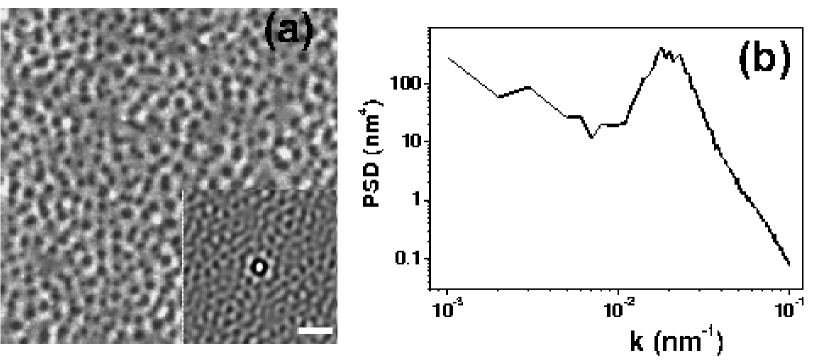
General considerations
In general, the behaviors found for ripple and dot nanopattern formation are analogous. Nevertheless, the ripple patterns present specific properties, due to the anisotropy of the process, such as ripple orientation, ripple propagation and shadowing. Analyzing the behaviors reported for the changes of both pattern morphologies with other parameters, the following map of trends can be drawn (we collect the main experimental observations in tables 1 and 2):
-
•
IBS patterns are produced with different ion species, even with those implying reactive sputtering.
-
•
IBS patterns are produced on a large variety of substrates: amorphous, semiconductors and metals.
-
•
The pattern symmetry reflects that of the experimental set-up (i.e., anisotropic or isotropic).
-
•
In general, the pattern in-plane order increases with fluence (i.e, sputtering time).
-
•
Frequently, the pattern wavelength coarsens with time to finally saturate.
-
•
The surface roughness initially increases sharply to later on either saturate or increase at a lower rate.
-
•
At low temperatures, the pattern wavelength does not depend on target temperature and ion flux, but it increases with ion energy.
-
•
Ripple patterns:
-
–
Ripples run perpendicular or parallel to the ion beam projection direction depending on the ion beam incidence angle.
-
–
Ripples propagate with a non-uniform velocity.
-
–
Shadowing effects appear in the ripple temporal evolution for long sputtering times and large values.
-
–
Ripples are produced by ions with energies ranging from just a few hundreds of eV up to eV.
-
–
At high temperatures, increases with target temperature following the Arrhenius behavior and decreases with ion flux and ion energy.
-
–
-
•
Dot patterns:
-
–
Patterns are produced mainly with in-plane hexagonal order but also with square symmetry (only for oblique incidence and rotating targets).
-
–
To date, dot patterns are only produced by low-energy ions.
-
–
Different dependences with target temperature have been found implying either no change, increase or decrease of with increasing target temperature. In addition, for InP the pattern symmetry changes from hexagonal to square with increasing temperature.
-
–
In general, the behaviors for ripple patterns seem to be better established than for dot patterns. This may be related to the fact that dot pattern production by IBS is relatively recent. In particular, the dependence of the morphological properties of these patterns with temperature, ion energy and fluence has to be systematically addressed in order to obtain a more general picture of the nanopatterning process. On the other hand, both types of IBS patterns share many behaviors, which is consistent with the corresponding theoretical models.
Also, there is a further experimental issue to be addressed: the possible influence of technical parameters on IBS pattern production. This important problem has been only studied by Ziberi and coworkers Ziberi_2004 . They obtained that the settings of the Kaufman ion-gun, the one that they employed, can affect the IBS nanopattern. In particular, they found that the divergence of the ion beam as well as the angular distribution of the ions within the ion beam influenced the pattern formation. If this happens already for a given ion-gun, we should likely expect some differences also when using other ion-gun types. Thus, it is convenient to perform systematic experiments on different targets and under different experimental conditions with the same equipment. This approach would allow a more direct comparison and contrast of the different experimental findings, which also would contribute to improve contrast between these results and the theoretical predictions.
| Oblique incidence | ||||
| Temperature | Flux | Time | Energy | |
| decreases Habenicht_2001 | Chini_2002 | |||
| NR | NR | Habenicht_2002 | NR | |
| Normal incidence | ||||
| Temperature | Flux | Time | Energy | |
| const. Facsko_2001 | (i.e. coarsening) Bobek_2003 ; Gago_2001 ; Gago_2002 ; Ozaydin_2005 ; Tan_2006 ; Xu_2004 | Facsko_2001 | ||
| decreases Gago_2006b | NR | NR | ||
| Order | Hexagonal | Hexagonal Facsko_2001 | Hexagonal (enhancement with time) Bobek_2003 ; Gago_2006 | Hexagonal Facsko_2001 |
| Oblique incidence with rotating substrate | ||||
| Temperature | Flux | Time | Energy | |
| increases with Frost_2000 | NR | Increases Frost_2000 ; Ziberi_2006c | ||
| increases with Frost_2000 | increases Frost_2000 ; Ziberi_2006 | Frost_2000 | Increases Frost_2000 ; Ziberi_2006c | |
| Order | Frost_2004 | NR | Increases Ziberi_2006c | |
3.2 Pattern formation in single-crystal metals by ion beam sputtering
The general observation of ripple and nanodot formation by off-normal and isotropic ion beam irradiation is only valid in the case of amorphous materials or for those that amorphize upon ion bombardment, such as single-crystal semiconductors. The case of metals should be treated through a different approach since the above properties do not occur. For example, ripples can be produced at normal ion incidence, or isotropic patterns may be formed under off-normal irradiation Rusponi_1997 . A large number of experimental results reported in metals has been compiled by Valbusa et al. Valbusa_2002 .
The peculiar behavior of metal surfaces relies in the nature of the metallic bond. Due to its non-directional character, metals do not amorphize upon ion bombardment, at least for low fluence and up to energies of a few keV Valbusa_2002 . Therefore, the surface retains its properties, the ion bombardment being only responsible for producing vacancies or vacancy aggregates at the surface Costantini_2001 , which increase the already large surface diffusion in these systems. Another relevant constraint for surface diffusion in metals comes from the presence of Ehrlich-Schwoebel (ES) energy barriers for adatoms to descend steps Ehrlich_1966 ; Schwoebel_1966 . These contributions add more complexity to surface nanostructuring by IBS in the case of metals.
The diffusive regime Valbusa_2002 for pattern formation in metals appears when the ES energy barrier or a preferential diffusion path determines the final pattern characteristics. In this regime, the erosion process is limited to incorporating a larger number of diffusive particles (such as atoms or vacancies) that align along the more thermodynamically favorable directions. This means that, in contrast with amorphous or semiconductor materials, the intrinsic properties of the surface reflect onto the resulting surface pattern. For example, the pattern will reflect the intrinsic isotropic characteristics of the material as in the case reported for Pt(111) by Michely et al. Michely_1991 . In the presence of diffusion anisotropy, as shown in Fig. 20 for Ag(100) Rusponi_1997 , ripples may be observed even under normal ion incidence, or the ripple orientation may vary with temperature. In this context, temperature governs thermal activation of diffusion pathways, leading under certain conditions to isotropic or anisotropic configurations. Additional relevant conclusions extracted from Fig. 20 are that the pattern wavelength increases with temperature as a result of enhanced surface diffusion and that the pattern coarsens with sputtering time. It has also been observed that the pattern wavelength under this diffusive regime depends only slightly on the ion energy.
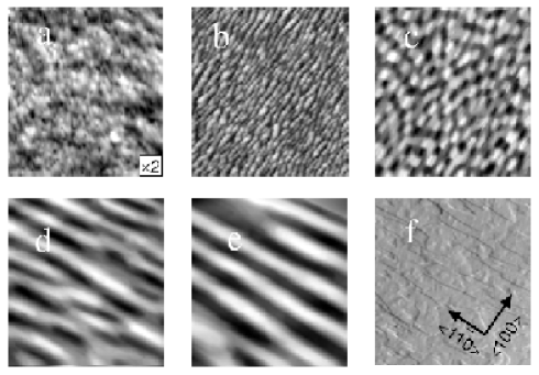
The erosive regime in metals Valbusa_2002 is attained only for near glancing incidence angles and at low temperatures in order to inhibit thermal surface diffusion. In this regime the pattern formation can not be correlated with any symmetry of the surface, such as the orientation of the crystal. This fact is shown for Cu(110) surfaces in Fig. 21 where the ion beam projection is modified with respect to the surface orientation without relevant change on the pattern characteristics Rusponi_1998 . This implies that IBS patterns can be aligned in directions that are not thermodynamically favorable, this fact being one of the major potentials of surface nanostructuring by IBS in contrast with other techniques such as MBE. In this regime, the ripples are parallel to the beam direction, their wavelength depends linearly with the ion energy and both, wavelength and roughness, increases with fluence Valbusa_2002 .
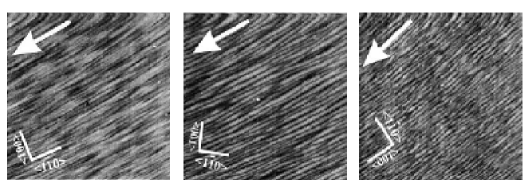
Finally, ion bombardment of metals does not always results in the formation of a regular pattern on the surface. In this case, the surface may additionally display kinetic roughening or not depending on the conditions. An example of these results was obtained by Krim et al. Krim_1993 on Fe surfaces bombarded with 5 keV Ar+ at .
The different parameter windows for pattern formation, smoothening or roughening have been studied by Chason et al. Chason_2006 for Cu(001) surfaces as a function of ion dose and target temperature. In this scheme, the surface remains flat for low ion fluxes and high temperatures whereas it roughens for high fluxes and low temperatures. For intermediate temperatures (200-350 K) the diffusive regime dominates and, finally, high ion fluxes and high temperatures imply an erosive regime.
3.3 Pattern formation in thin metal films by ion beam sputtering
In the previous section, we have seen that ripples can be also produced by IBS on single-crystal metals for which ES energy barriers Ehrlich_1966 ; Schwoebel_1966 play such a crucial role, influencing the stability of the ripple morphology even at room temperature Valbusa_2002 . However, a different scenario has to be considered for IBS nanostructuring of thin metallic films. These systems are usually polycrystalline and mainly formed by grains that are randomly oriented, and with sizes that are usually much smaller than the film thickness Jeffries_1996 ; Wei_1998 . For such systems, the existence of ES barriers becomes improbable due to the lack of well-defined atomic steps at the surface Jeffries_1996 . These facts support the effective existence of an isotropic surface diffusivity rather than an anisotropic one. In this sense, thin metal films subject to IBS nanostructuring processes would be akin to the case of amorphous or amorphizable surfaces. Two groups have reported their findings for such systems.
Karmakar and Ghose have produced ripple structures on Co, Cu, Ag, Pt and Au thin film (thickness in the 30-200 nm range) surfaces irradiated at 80∘ by 16.7 keV Ar+ ions Karmakar_2004 . They found that the ripple wavelength as a function of the target element was qualitatively consistent with the behavior predicted by Makeev et al. Makeev_2002 . Under this approach depends mainly on the lateral and longitudinal straggling widths of the ion cascade, as well as on the angle of incidence. Karmakar and Ghose obtained these values from the computer code SRIM Ziegler_2006 , and found qualitative agreement between the theoretical and experimental behaviors. However, there are sizeable quantitative differences. This is not new, quantitative disagreement between calculated and measured values having been previously pointed out by different groups Kim_2003 ; Facsko_2001 ; Gago_2006b . Another interesting finding refers to the stability of the induced ripple patterns at room temperature Karmakar_2004 in comparison with those produced on single crystals Valbusa_2002 . This fact is an indication that the thermally activated diffusion energy barriers in thin polycrystalline films are comparatively higher than in single crystal metal surfaces, which agrees with the assumption on the absence of ES barriers. In fact, measurements of activation energies for adatom surface diffusion on various polycrystalline materials are consistent with this result Rossnagel_1982 . The studies of Stepanova and coworkers consisted in the irradiation by a 1.2 keV Ar+ ion beam of a 50 nm-thick Cu film deposited on glass or silicon substrates Stepanova_2005 ; Stepanova_2006 . When the irradiation angle was oblique, at , a clear ripple pattern was induced. These experiments allowed to discard any possible influence of the underlying substrate (either glass or silicon) in terms of composition and crystalline structure on the production of ripple patterns on the top metal thin film. Another set of experiments was performed under the same conditions but at normal incidence. In this case, a self-assembled network of 20 nm-sized ring-like Cu features was observed on a SiO2 substrate after 1.2 keV Ar+ beam etching of the Cu/substrate interface Stepanova_2005 .
The previous studies suggest that IBS of interfaces might be a reasonable process to fabricate metal nanopatterns on nonmetallic substrates. Also, the specific properties of these thin film polycrystalline metal systems make them suitable of study through to the same approach that is employed to understand IBS nanopatterning of amorphous/amorphizable surfaces.
4 Theoretical approaches
As seen in the previous sections, typically the IBS induced nanopatterns fully evolve in macroscopic time and length scales (minutes and several microns, respectively). It is at these scales where, e.g., interaction among ripples can be seen to lead to order improvement with fluence or, rather, to eventual disorder in heights. Although detailed knowledge on the phenomenon of sputtering is rapidly and consistently developing through (microscopic) Molecular Dynamic type of studies (see e.g. Bringa_2002 ; Nord_2003 and references therein, and Sec. 2), the scales that are currently reachable to these methods remain in the 1 ms and 50 nm ranges. Monte Carlo (MC) and continuum methods (CM) can probe larger scales so that these are the approaches that we will consider in what follows.
4.1 Sigmund’s theory of sputtering
As mentioned in section 2.5, in a classic work Sigmund analyzed the kinetic transport theory of the sputtering process Sigmund_1969 . Assuming an infinite medium, he found that, in the elastic collision regime at the energies of a few keV where electronic stopping is not dominating, the deposited energy can be approximated by a Gaussian distribution near its maximum. Specifically, the density of energy spread out in the bulk by an ion with kinetic energy is given by
| (5) |
where the origin of the coordinate system is placed at the impact point of the ion within the surface; is aligned along the ion beam direction, and and belong to the perpendicular plane to , see Fig. (22).
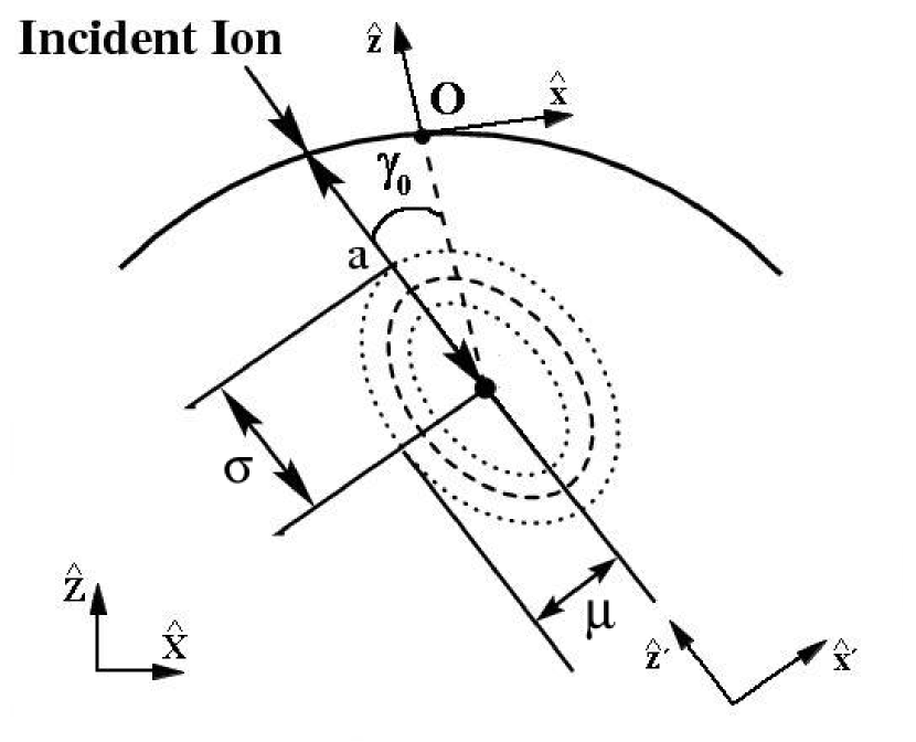
In Eq. (5), is a normalization constant and, due to the initial momentum of the ion, the maximum of energy deposition occurs at a distance along the ion trajectory inside the bulk. The longitudinal and transversal straggling widths of the distribution are and respectively. If mass differences between substrate and ion are not too large, the quality of the approximation is reasonable and expression (5) provides a good approximation for polycrystalline and amorphous targets Sigmund_1969 . Despite the fact that depends on the microscopic details of the interactions between the ion and the bulk, at intermediate energies ( keV), it is usually considered to be proportional to . Within this range of energies, , and are of the order of a few nanometers. This point will be relevant when information about the evolution of the topography is obtained.
As we noted above, correlation of the sputtering yield with the surface geography is a crucial issue. In Ref. Sigmund_1973 , Sigmund showed that the topography of the surface can indeed influence the magnitude of the rate of erosion and, provided an analytical description that describes the increase of yield for geometries different from the flat morphology. It is assumed that the speed of erosion at a point on the surface is proportional to the amount of energy deposited there by the ions, with a proportionality constant that is characteristic of the substrate and depends on the atomic density of the target , the atomic energy of connection in the surface , and a proportional constant which is related to the square of the effective radius of the potential of effective interaction according to
| (6) |
Under these hypotheses, it is possible to obtain the mathematical expression for the rate of volume eroded in . This is simply given by
| (7) |
The integral extends to the region where the impact of the ions contributes to energy deposition at . The term represents the local flux. We have specified its dependence with to show the corrections due to the local geometry to the homogenous flux . From (7), Sigmund derived the rate of erosion for diverse artificial geometries, such as a flat surface followed of an inclined plane or a vertex, in the case of normal incidence.
The previous description, as already observed by Sigmund Sigmund_1973 , and briefly noted in Sec. 2.5 above, implies the occurrence of a morphological instability. Let us suppose that we irradiate a certain surface with an homogenous flow, as shown in Fig. 23. We can verify that distances and are smaller than and due to the geometry of the interface. This implies that, for this energy distribution, the penetrations of ions at and induce large energy deposition at than the impacts on and at . As the rate of erosion is proportional to the deposited energy, erosion is faster at than at . Thus, valleys are excavated more quickly that crests amplifying initial differences in heights. Sigmund suggested that an alternative process that flattens the surface must exist and he proposed atomic migration as a mechanism to correct this instability.
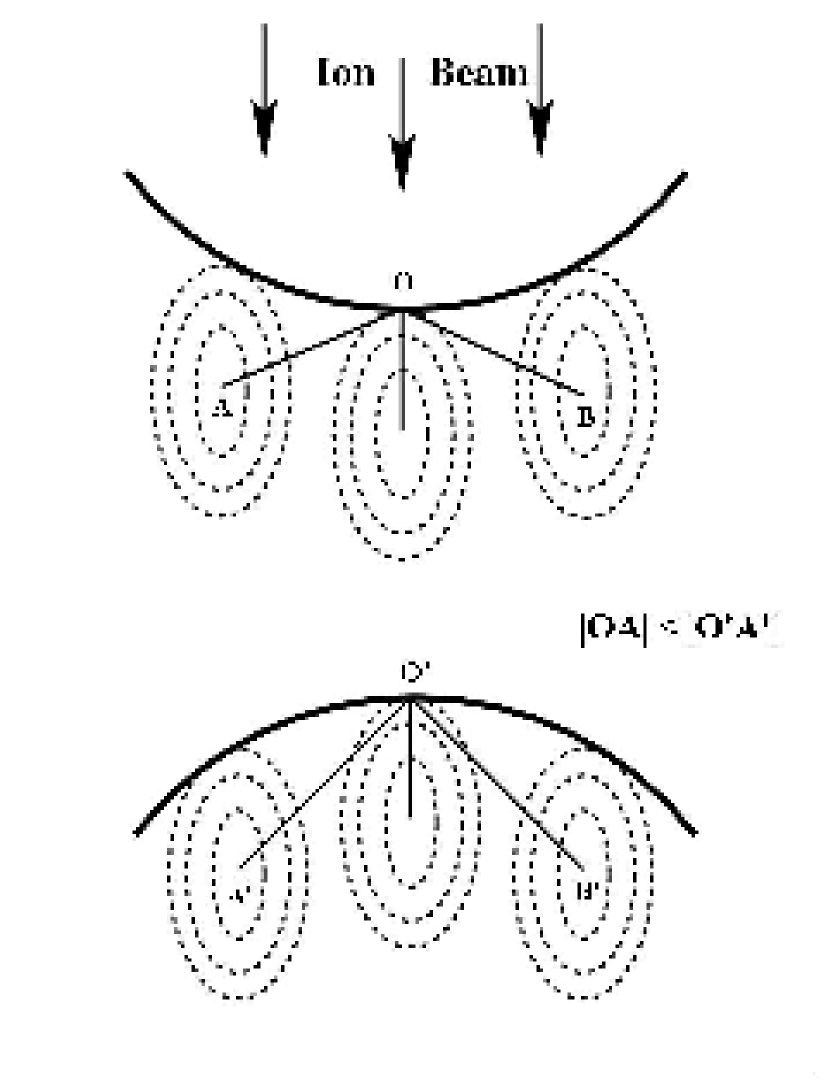
The theory of Sigmund is the basis for most of the later continuum approaches to the dynamics of surfaces undergoing by IBS. In principle, as a theory of sputtering, and as mentioned in Sec. 3.1, it is known to have limitations. Within the range of energies we are considering, two of the most conspicuous ones refer to: (i) the behavior of the sputtering yield for large incidence angles; (ii) crystalline targets. Related with the former, Sigmund’s theory predicts an steady increase of the yield with incidence angle, not being able to account for the well-known decrease of at glancing incidence due to more efficient projectile reflection and channeling effects at the surface. Nevertheless, recent continuum studies Chen_2005 have shown that improved distributions accounting for this effect (see in Chen_2005 and Nastasi_1996 ) do not modify qualitatively the morphological predictions to be derived below from the energy distribution (5). Similarly, channeling effects limit in principle the applicability of Sigmund’s theory to crystalline solids [point (ii)], by inducing sizeable departures from the energy distribution as described by (5). Thus, different distributions must be considered, as done e.g. in Feix_2005 for the particular case of Cu targets. However, as seen in this work, again these modifications do not alter the qualitative morphological implications of the continuum theories to be described below, which justifies (at least for temperatures at which Ehrlich-Schwoebel barriers do not dominate surface diffusion Valbusa_2002 ) the strong similarities in nanopattern formation by IBS on metals, as compared with amorphizable targets.
As a morphological theory, again Sigmund’s Sigmund_1973 has some limitations: it does not predict the alteration of the morphology during the process for scales much larger than penetration depth for ions; as surface diffusion is not considered, the wavelength of the pattern needs to be of the order of the length scales appearing in the energy distribution Eq. (5); the effects of surface shadowing or redeposition are not considered; it does not predict the time evolution of the morphology and how it affects the rate of erosion. Thus, an additional physical mechanisms and a more detailed description of the surface height are needed in order to derive a morphological theory with an increased predictive power.
4.2 Monte Carlo type models
(Kinetic) MC methods have a long and successful tradition in the context of IBS Ziegler_1985 ; Ziegler_2006 . For our morphological purposes, they have found increased application during the last decade. Their main advantage is that, in principle, they allow to make a more direct connection to microscopic relaxation mechanisms than e.g. continuum approaches. In addition, they do not require analytical approximations, lending themselves, rather, to numerical simulations that can reach reasonably large scales (around 10 s and around 100 monolayers of erosion). However, as compared with CM, dependencies of observables with physical parameters are less direct, accessible scales are shorter and universal (i.e. substrate/ion independent) properties are harder to assess unambiguously. Actually, the two types of approaches —MC and CM— to some extent complement each other so that, although our focus will be mostly on CM, we consider shortly some of the main results of the most recent MC studies.
In order to access large scales as mentioned, MC methods consider physical relaxation rules in which microscopic details —such as specific interactions among ions and target atoms— are coarse-grained out and replaced by effective dynamical rules. These have to represent, on the one hand, the events leading to erosion by sputtering and, on the other hand, competing relaxation mechanisms such as surface diffusion. For the sputtering processes, starting with the study of Cuerno_1995b many MC models consider an erosion rule that is either a discretization Cuerno_1995b or, rather, a direct implementation Hartmann_2002 ; Tok_2004 ; Brown_2005b ; Yewande_2005 ; Yewande_2006 ; Chason_2006b of Sigmund’s continuum law for energy deposition due to linear collision cascades (with corrections for large local incidence angles Stepanova_2004 ; Stepanova_2006 ). Actually, this energy deposition rule has been extended even to MC studies of different physical processes, such as e.g. laser induced jet chemical etching Mora_2005 . Nevertheless, other MC models do consider more microscopic (albeit still approximate) rules for erosion, such as the binary collision approximation similar to that employed in SRIM simulations Ziegler_1985 ; Ziegler_2006 , as done in the works by Koponen and collaborators Koponen_1996 ; Koponen_1997 ; Koponen_1997b ; Koponen_1997c ; Koponen_1997d . Or else, still different approaches to the sputtering events consider dynamical creation of surface adatoms/advacancies Chason_1997 ; Murty_1998 ; Strobel_2001 .
As for the additional surface relaxation mechanisms, most of the works mentioned restrict their nature to surface diffusion (there being additional physical possibilities, such as redeposition, viscous flow, etc.) for adatoms and/or advacancies. The rates for diffusion vary among the different studies, being either dependent on the energies of the initial and final states —within a local equilibrium approximation— or, rather, following temperature-activated Arrhenius laws; see a recent overview in Chason_2006b .
Although there are some differences in the morphological dynamics predicted by the various MC models, there is agreement in a number of basic properties, such as: (i) the occurrence of a morphological instability at small/intermediate times, that is well described by CM; (ii) at oblique ion incidence, the non-linear evolution of the ripples as reflected in their non-uniform transverse motion; (iii) the saturation (stabilization) of the surface roughness at sufficiently long times. Differences among various models do occur in their predictions: for instance, in some models the dominant pattern wavelength remains fixed in the course of time Cuerno_1995b ; Koponen_1996 ; Koponen_1997 ; Koponen_1997b ; Koponen_1997c ; Koponen_1997d ; Chason_2006b , while in other models a consistent wavelength coarsening phenomenon occurs Hartmann_2002 ; Stepanova_2005 ; Yewande_2005 ; Yewande_2006 ; Chason_2006 ; Stepanova_2006 with properties (like the coarsening exponent value) that depend on physical parameters like the substrate temperature. Then, there are properties —such as the the kinetic roughening of the interface height fluctuations at long times— about which some of these studies do not extract conclusions (if they do not focus on such large scale issues), while other works reach different quantitative results (regarding e.g. the values of the scaling exponents, although most predict their occurrence).
4.3 Continuum descriptions
The wide separation in scales between the microscopic events that take place in the target during the irradiation process, and the large-scale response of its surface morphology recall a similar between microscopic and collective motion in the case of e.g. fluid dynamics. Thus, it is natural to expect Cuerno_2007 that some continuum description in the spirit of, say, the Navier-Stokes equations might be appropriate in the case of nanopattern formation by IBS. The advantage of continuum descriptions, if available, is that they provide compact descriptions of complex physical phenomena. Moreover, these frameworks are frequently more efficient computationally for the study of large scale properties, whose generic properties can be faithfully described by them Krug_2004 . Nevertheless, for the type of non-equilibrium phenomena which are our present focus, the relevant continuum equations are most times non-linear, their study requiring either analytical approximations or numerical simulations.
Dynamics of the surface height
In order to put forward a continuum description of these non-equilibrium systems, Sigmund’s theory Sigmund_1969 ; Sigmund_1973 constitutes an ideal starting point. This is so because Eq. (7) already provides an explicit expression for the most relevant kinetic quantity describing the sputtering problem, namely, the local velocity of erosion. In turn, one may add different contributions to the right hand side of this equation if additional physical mechanisms contribute to the local variation of the target height, and this has indeed been done in order to improve the physical description. Still, for theoretical work, (7) is technically a very complex expression. The insight of Bradley and Harper (BH) Bradley_1988 is that, under reasonable physical approximations, (7) becomes a closed time evolution equation for a single physical field, the target height above point on a reference plane. It is within such (simple) single-field approach that most of the recent continuum descriptions have circumscribed themselves. However, we will see in this section that this program encounters consistency problems —that question its physical applicability— unless the dynamics of additional independent fields are taken into account. The evolution of these fields —e.g. the density of species that diffuse on the surface— also modifies the local height velocity. This does not mean that a description by a closed equation for the height field is inappropriate but, rather, that to correct such description, one has to necessarily take into account for its derivation physical mechanisms that complement Sigmund’s formula. In this section we recall the main results obtained along BH’s pioneering “single-field” height approach, while the next section will (mostly) consider recent developments that incorporate the dynamics of additional physical fields to the continuum description.
Bradley and Harper’s theory
Bradley and Harper (BH) Bradley_1988 derived a partial differential equation to describe the evolution of the morphology assuming that the variation in the height of the surface is smooth when seen at a scale that is comparable with the average penetration length of the ions. By expanding the target height as a function of the surface geometry up to linear order in the surface curvatures, they obtained a closed evolution equation for the surface height. In the following we recall the main steps of the derivation.
Define a local coordinate system with the axis oriented along the surface normal at and the and axes lying on the perpendicular plane to (i.e. in the tangent plane through ) where is aligned along the projection of the ion beam onto this plane as shown in Fig. 22.
Assuming that the function which represents the height of the surface, , is single valued and varies smoothly, we can approximate the height in the neighborhoods of as
| (8) |
where and are the principal radii of curvature. The simple formula (8) is enough to our purposes for two different reasons. First, for smooth surfaces the average penetration length is smaller than the radii of curvature and only ions penetrating the target a distance smaller than from the point contribute appreciably to erosion there (since energy deposition decays with distance as a Gaussian). Second, it is assumed that the surface principal directions —along which curvature is maximized or minimized— are aligned along the and axes. This holds at least for the cases in which structures are aligned either parallel or perpendicular to the projection of the incident beam (which is the usual case, as observed in previous sections).
We can obtain the local speed of erosion at using Eq. (5). To this end, one needs to change coordinates in Eq. (5) to the frame in Fig. 22 and take into account that the local flux of ions at any point of the surface, , is related to the homogenous flux, , by , where is the angle between the beam direction and the local normal direction. By Taylor expanding to linear order in the curvature radii and using Eq. (7), BH obtained an expression for the erosion rate at that reads
| (9) |
where the functions , and only depend on , the local angle of incidence and the distances, , and of Eq. (5).
Once the dependence of the erosion rate with the local morphology has been obtained, we can obtain a continuum equation for the local surface height, , in the laboratory system of reference sketched in Fig. 22. Thus, we define the component to be perpendicular to the initial surface, as parallel to the projection of the ion beam onto the initial flat surface, and as perpendicular to and . Within our linear approximation (see Makeev_2002 ) we can assume and , where is the angle between the ion beam and the normal to the uneroded surface, and using (9) one obtains Bradley_1988
| (10) |
with
| (11) |
where any nonlinear terms have been neglected and we have used and . Here, and are always positive and, therefore, the surface height decreases at constant speed .
In order to get information about the evolution of the surface, we will assume the following perturbation with spatial frequencies and , and amplitude at time :
| (12) |
If we substitute this expression into (10), we obtain the real part of the dispersion relation, . This reads
| (13) |
and the imaginary part is
| (14) |
The imaginary part of indicates the magnitude and direction of the speed of transverse in-plane motion of the disturbances. Since is an increasing function of Bradley_1988 , the perturbation moves in the direction (that is, upstream with respect to the projection of the beam). On the other hand, describes the rate at which the amplitude of a perturbation with wave-vector grows or decays with time. Given that at small angles of incidence Bradley_1988 and , any spatial perturbations on the initial surface grow exponentially in time. Since is positive at the bottoms of the valleys, at these points the rate of erosion is larger than at the top of the crests where . Therefore, the negative signs of and are the mathematical expression of Sigmund’s morphological instability. At these small incidence angles, moreover, and perturbations grow faster along the axis than along the . Hence, at these angles, the ripples crests are perpendicular to the projection of the ion beam onto the surface as observed experimentally. For the critical angle , one precisely has while for larger angles and the ripple crests align with the ion beam projection.
These results predict some of most basic experimental features of IBS ripples but, without an additional mechanism which stabilizes the system, disturbances of arbitrarily small length-scales would increase exponentially without bound. On the other hand, from Eq. (10) one would expect the ripple wavelengths to be of the order of the distances involved in the description, that is to say, of the order of the penetration length . This does not happen, rather, the experimental ripple wavelengths are frequently almost two orders of magnitude larger than . In order to solve these problems, BH incorporate the effects of the surface diffusion of thermal origin by introducing an analogous term to that derived by Mullins Mullins_1957 for isotropic surfaces. With this aim, a term is included into (10) to obtain the following linear equation which describes the evolution of
| (15) |
Proceeding as in Eqs. (12)-(14), the real part of the dispersion relation modifies into
| (16) |
that is negative for wave vectors of sufficiently large (i.e. short length scales). However, there is a band of unstable long-wavelength modes for which (16) is positive. The orientation and wavelength of the observed ripple structure corresponds to that mode which maximizes (16); this is if the ripples are oriented along the axis as a result of , or if the ripples are oriented along the axis as a consequence of . With the aim of obtaining an order of magnitude estimation of this quantity, Bradley and Harper deduced that for normal incidence, a sputtering yield of 2 atoms per ion, nm, and a typical value cm4 s-1, the value of the linear wavelength is m, in reasonable agreement with the typical distance between ripples observed experimentally.
If surface diffusion is thermally activated, as effectively occurs for high temperatures and small flows, it is easy to obtain how the wavelength of the pattern varies with the temperature, . Since do not depend on and assuming that verifies , where is the energetic barrier to activate surface diffusion and is the Boltzman’s constant, the linear wavelength must verify . On the other hand, it is also possible to obtain a relationship between ripple wavelength and the kinetic energy and flux of ions, and , respectively. Assuming that , and are proportional to and independent of , one gets and .
Working still within a linear approximation to the surface height in a similar spirit to the introduction of surface diffusion in (15), some alternative physical mechanisms have been proposed, specially in order to account for the lack of pattern (ripple) formation at either low temperatures Chason_1994 or small angles of incidence Carter_1996 . Thus, a term of the form added to the (Fourier transformed) right hand side of Eq. (15) can describe the effect of viscous flow in the bulk onto the surface dynamics, with being a coefficient that depends on the surface free energy and bulk viscosity Mullins_1957 ; Mullins_1959 . For low enough temperatures at which thermal surface diffusion is hampered, bulk viscous flow could dominate the surface dynamics even to the extent of preventing ripple formation for oblique angle incidence Chason_1994 or dot formation for rotating substrates Cirlin_1991 . Alternatively, the fact that a fraction of the sputtered atoms that move close to the surface are recaptured has led to arguing Carter_1996 for the effective description of such a process by inclusion of a term with the form , where would be a positive, angle dependent coefficient. We will see later that also direct knock-on sputtering events would have effectively an analogous continuum description, thus corresponding to stabilizing mechanisms that can counterbalance Sigmund’s instability.
Higher order corrections
As we have seen, BH’s linear theory already predicts many important features of the nanopatterning process, but leaves out a number of additional properties. For instance, it cannot predict saturation of the ripple amplitude or their non-uniform lateral motion. In order to account for these features, one needs to generalize the BH theory, the most natural procedure being the extension of their perturbative expansion in surface derivatives in (5)-(7) up to higher order. In this process one needs to approximate the surface height locally through a Taylor expansion, such as BH did, only that the order of approximation is higher. Along the way, not only non-linear contributions do arise, but also corrections appear to previous linear terms. These thus provide contributions of erosive origin to linear relaxation mechanisms such as transverse pattern motion, and surface diffusion. This program has been carried out in Cuerno_1995 ; Makeev_1997 ; Makeev_2002 . The result is the following equation (the coefficients with various indices appearing in this and the following height equations are not to be confused with the pattern wavelength)
where all coefficients depend on the experimental parameters from Sigmund’s theory Makeev_2002 , like in BH’s equation (10), which now becomes a linear low order approximation of Eq. (4.3). In the first line of (4.3), and except for the constant average velocity , all terms provide linear and non-linear contributions to the transverse ripple motion. The second line reflects the dependence of the sputtering yield with the local curvatures (as in BH’s equation) and slopes, while the third line contains (linear) surface diffusion terms that include both thermal (as in BH) and erosive contributions. This type of contributions break in general the symmetry while respecting symmetry under , dependence of all parameters on the incidence angle being such that for normal incidence rotational in-plane symmetry is restored, Eq. (4.3) becoming the celebrated Kuramoto-Sivashinsky (KS) equation:
| (18) |
where we have used that, for , , , , Makeev_2002 .
The main morphological implications of Eqs. (4.3) and (18) have been discussed elsewhere Makeev_2002 . Here, we briefly mention the main conclusions. First of all, from the point of view of these equations, the behavior predicted by BH appears as a short-time transient, and all BH predictions —on the dependence of e.g. the ripple structure with incidence angle— still carry over here. Moreover, for temperatures at which surface diffusion is activated, the dependences of the ripple wavelength with energy, temperature and flux are as in BH, at least for short to intermediate times. If is low enough that the only contribution to surface diffusion is from erosive origin, these dependencies are modified and compare better with experiments at low temperatures, see Makeev_2002 and Sec. 3 above. For intermediate to long times, the nonlinear terms in Eqs. (4.3), (18) are such that the exponential growth of the ripple amplitude is stabilized, yielding to a much slower power-law increase of e.g. the surface roughness with time. At normal incidence, the surface displays kinetic roughening for long time and length scales, and this is also the case at oblique incidence, as long as the nonlinearities have the same signs. Otherwise, Eq. (4.3) features cancellation modes as first identified in the anisotropic KS equation, that is the following particular case of Eq. (4.3) in which the propagative terms with coefficients and (being arguably irrelevant to the asymptotic limit) are simply neglected Cuerno_1995 ; Rost_1995 :
Cancellation modes are height Fourier modes with wave vector in the unstable band, for which the non-linear terms cancel each other, leaving the system non-linearly unstable, and inducing ripples which are oriented in an oblique direction that is parallel neither to the nor to the axis Rost_1995 .
Eq. (18) has, on the other hand, the capability (beyond linear equations such as that of BH) of predicting both “dot” and “hole” production, depending on the sign of the non-linear parameter , which in turn depends on the characteristics of Sigmund’s distribution Kahng_2001 . However, conspicuous non-linear features still remain beyond description by the KS equation (18) and its generalizations (4.3), (4.3). First, the “dot” or ripple structures described by these non-linear equations are characterized by a dominant wavelength that remains fixed in time and does not coarsen for any parameter values, so that experiments in which coarsening occurs cannot be accounted for. A stronger limitation is that the patterns described by (4.3), (18), (4.3) disorder in heights to the extent that the size of ordered domains of ripples or dots essentially restricts to a single structure. There is thus no lateral ordering of the dots or ripples. Actually, the KS equation is known as a paradigm of spatio-temporal chaos in the wider field of Non-Linear Science Mori_1997 .
Following the program sketched at the beginning of this paragraph, a natural step is to carry on still further the perturbative study of Sigmund’s local velocity of erosion pioneered by BH. At the present stage, one could close Eq. (18) (we now consider normal incidence for simplicity) by including non-linear terms that are quadratic in the height field and fourth order in space derivatives, reaching an equation of the form (in reference frame comoving with the eroded surface)
| (20) |
Indeed, such a higher order generalization has been performed Kim_2004 . However, the expressions of and in terms of Sigmund’s parameters are such that the coefficients of the two nonlinearities in Eq. (20) have the same signs for all physical parameter values. Unfortunately, as shown shortly after Castro_2005b ; Kim_2005 , this introduces cancellation modes that seriously question the mathematical validity of (20) for our physical system: writing the equation in Fourier space, we get
| (21) |
where denotes Fourier Transform. For the unstable mode (that indeed occurs physically, see the experiments of IBS of Pd(001) in Kim_2004 ; Castro_2005b ) such that , the nonlinear terms cancel each other, so that the amplitude of this mode explodes exponentially. We are seemingly left with a matter-of-principle limitation, namely, the simpler theoretical approach that is limited to studying Sigmund’s local velocity of erosion (at sufficiently high linear and non-linear orders) meets mathematical limitations before being able to cover for the various experimental features of the patterns we wish to study.
In the following paragraph we will take a wider viewpoint in which the dynamics is more complete, in the sense that the surface height will be coupled to an additional physical field describing the flux of adsorbed material that diffuses on the near-surface layer. This procedure will be seen to provide an improved description solving some of the above physical and mathematical shortcomings. Before doing so, we note that additional studies exist that focus on the evolution of the height field only. Thus, the standard result in the field of Pattern Formation (see references in Paniconi_1997 ) that a linear damping in the KS equation induces the appearance of ordered patterns, has directly led to the proposition in Facsko_2004 of (a modified) damped KS equation to describe the experiments described in Sec. 3. This modified equation actually becomes the standard damped KS equation after an appropriate non-local time transformation Vogel_2005 . Although the natural anisotropic generalization has been duly proposed Vogel_2006 , these equations unfortunately do not allow much improvement in the continuum description of nanopatterning by IBS for several reasons: (i) there is no connection to phenomenological parameters (the equations are not derived from any model but are, rather, argued for on a phenomenological basis); (ii) damped generalizations of the KS equation are known (see Castro_2007 and references therein) not to allow for wavelength coarsening for any parameter values, which leaves out of these descriptions many of the experimentally observed patterns; (iii) similarly, at long times the fluctuations of the PSD function predicted by any of the damped generalizations of the KS equation are cut-off and do not show the type of power-law like behavior that is seen, even in experiments in which there is no coarsening Ziberi_2005 ; Ziberi_2006c . In contrast, a more successful extension of the BH-type approach has been its generalization in Chen_2005 to surfaces with steep slopes. Recall that starting with BH’s, all continuum approaches mentioned (in contrast e.g. with MC models) work within a small-slope approximation that allows neglection of higher order terms in Eqs. such as (4.3)-(20). Remarkably, a suitable generalization for arbitrary slope values has been seen in Chen_2005 to lead to a non-linear equation whose traveling wave (shock) solutions compare well with experiments on the motion of the walls of pits excavated by a FIB. These results possibly provide important clues for a more complete model of nanopatterning by IBS.
Coupling to diffusive surface species
Due to physical and mathematical considerations, the previous section leaves us with the need to enlarge the continuum description of nanopatterning by IBS. The expectation is that, by incorporating the dynamics of additional physically relevant fields, the effective height equation to be eventually derived improves its formal properties and its predictive power. Perhaps we could compare the situation with related fields such as e.g. the growth of thin films by physical or chemical vapor deposition (CVD) techniques. In CVD, for instance (see references in Cuerno_2007 ), the standard continuum description arises precisely from the coupling between the local (growth) velocity and the dynamics of the concentration field of the diffusing species that eventually will stick to the growing aggregate.
There have been various attempts in the IBS context to combine the surface dynamics as predicted by a BH-type equation, with the evolution of relevant surface species, such as adatoms, addimers and surface traps (see Erlebacher_1999 ; Chason_2001 and references therein). However, in this approach no explicit feedback mechanism is provided from the dynamics of such species onto the local variation of the surface height so that the dynamics cannot be described by a closed system of equations. On the other extreme, there is a recent proposal in which a full Navier-Stokes (thus, highly coupled) formulation is proposed to describe ripple transverse motion onto a glass surface Alkemade_2006 . Trying to reach a balance between complexity and completeness in the physical description, one can seek for a formulation that, while simpler than a full hydrodynamic model, still provides an explicit coupling between the surface topography and the evolution of the relevant diffusive fields. For the case of ripple dynamics in the different (macroscopic!) context of aeolian sand dunes Csahok_2000 , such is the spirit of the so-called “hydrodynamic” approach, in which one sets up a system of coupled equations that describe the height of the eroded substrate profile, , and the thickness of a mobile surface layer, . Although there are relevant differences between both physical systems —the size of the structures is roughly seven orders of magnitude larger in aeolian ripple formation than in IBS systems—, the similarity between the mechanisms of diffusion and erosion and the analogous form and behavior of the patterns in both systems seem to suggest that these processes could be modeled by similar formalisms.
This program has been followed in Refs.Aste_2004 ; Aste_2005 ; Castro_2005 ; Munoz_2005 , where the next equations are proposed to describe the evolution of the fields and :
| (22) | |||
| (23) |
In (22) and (23), and are, respectively, rates of atom excavation from and addition to the immobile bulk, measures the fraction of eroded atoms that become mobile, and the third term in Eq. (22) describes motion of mobile material onto the surface. In this way, local redeposition is allowed if Kustner_1998 , while the viscous near-surface layer is provided with a dynamics of its own Umbach_2001 .
In Refs. Aste_2004 ; Aste_2005 , a linear dependence of and with the local geometry of the surface is considered to study the linear stability of this system. These studies reveal that depending on the values of the parameters, the ripple orientation could be aligned in any target direction, one of the limitations of this model being that the model is not well defined in the absence of redeposition .
More detailed mechanisms of erosion and addition are explicited in Refs. Castro_2005 ; Munoz_2005 , where nonlinear terms for the rate of excavation are introduced. These additional mechanisms are seen below to induce richer pattern dynamics than previous models for the surface height only. Unlike Aste and Valbusa’s and aeolian sand ripples models, in Munoz_2005 the momentum in the direction of the projection of the beam directly transmitted from ions to superficial atoms is neglected. Rather, a diffusive term for mass transport onto the surface is considered that, in the case of isotropic amorphous materials, is given by , where is a thermally activated constant. Another feature of Castro_2005 ; Munoz_2005 is to consider a non-zero amount of mobile material, , even in the absence of excavation () o redeposition () which could be thermally induced. This term allows us to write the rate of addition in similar form to the Gibbs-Thompson expression for surface relaxation via evaporation-condensation, namely,
| (24) |
where is the mean nucleation rate for a flat surface (on the plane) and , describe variations of the nucleation rate with surface curvatures (and are positive if we assume that nucleation events are more likely in surface valleys than in protrusions). Note that, in (24), the full thickness of the mobile layer is affected by the shape of the surface.
In Munoz_2005 , a expression similar to the non-linear generalization (4.3) of BH’s local erosion velocity is considered for the rate at which material is sputtered from the bulk. If the beam direction is in the plane, we have,
| (25) |
where parameters reflect the dependence of on the local shape of the surface and are function of the angle of incidence, ion and substrate species, ion flux, energy, and other experimental parameters just as the coefficients of Eq. (4.3).
Oblique incidence
In a weakly nonlinear analysis of this system, the length-scale separation we have already mentioned between the time-scales associated with erosive and diffusive events is seen to play a crucial role. Thus, in particular the diffusive field relaxes much faster than the target height , making it possible within a multiple-scale formulation to solve perturbatively for the dynamics of the former and derive a closed effective equation for the evolution of the latter which, in the case of oblique incidence Munoz_2005 ; Munoz_2007 , reads
| (26) |
where these new coefficients are related to those of Eqs. (22)-(4.3) Munoz_2005 .
As in the nonlinear continuous theories shown in the previous section, the reflection symmetry in is broken in Eq. (4.3), but it is preserved in the axis. Equation (4.3) generalizes the height equations in Bradley_1988 ; Makeev_2002 ; Park_1999 within BH approach to IBS; the main difference between (4.3) and (4.3) is that additional terms appear in the later. These terms result important to correctly describe the evolution of the pattern as we will see bellow. To the best of our knowledge, Eq. (4.3) is new, and indeed has a rich parameter space. Numerical integration within linear regime retrieves all features of the ripple structure as predicted by the BH theory, i.e., dependence of the ripple wavelength with linear terms, and ripple orientation as a function of .
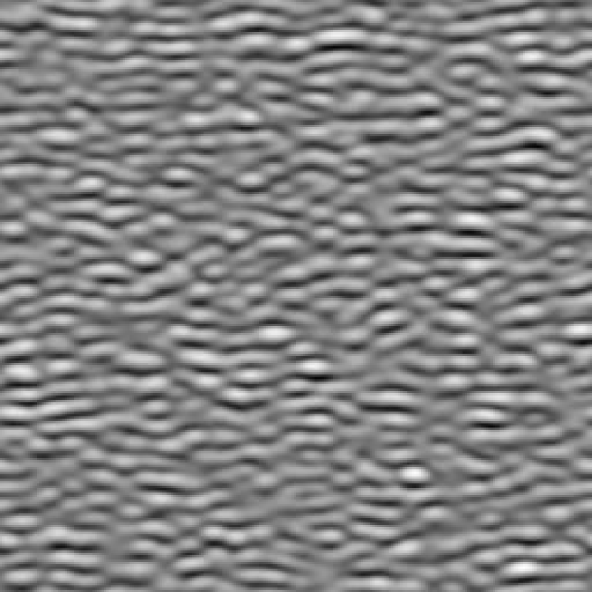
(a)
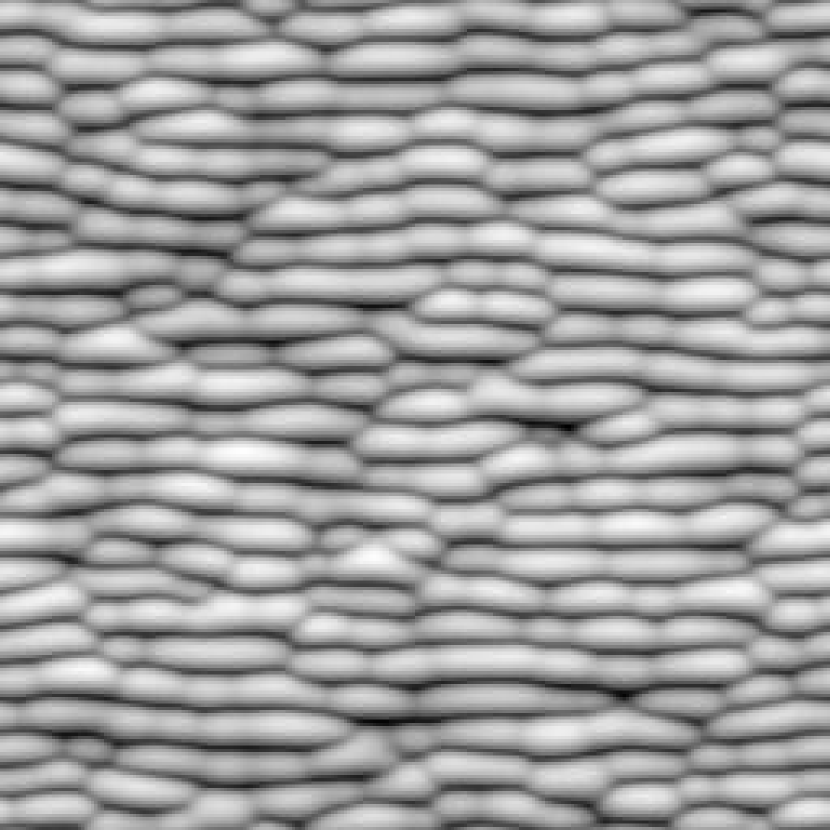
(b)
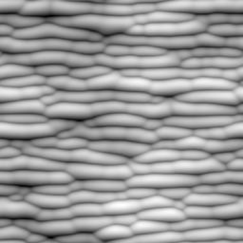
(c)
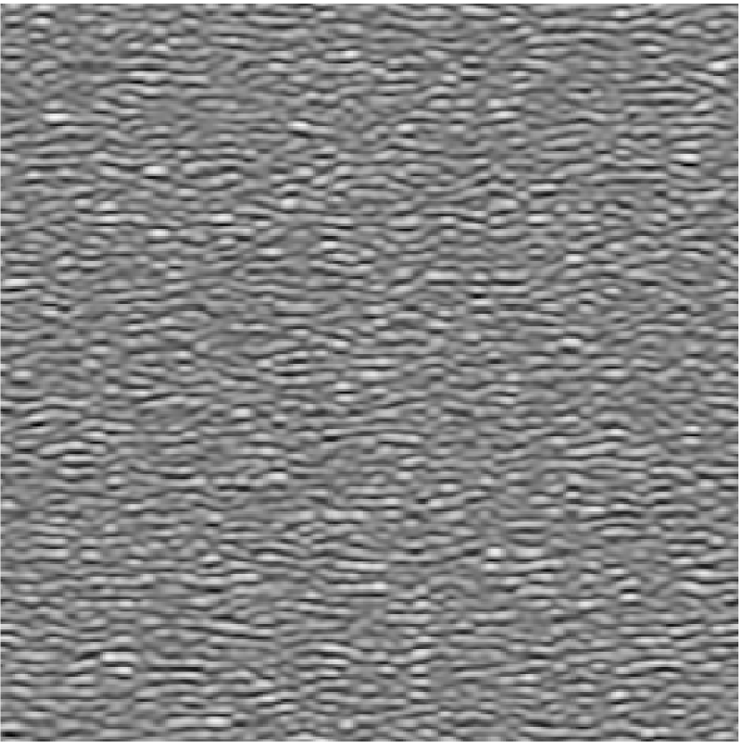
(d)
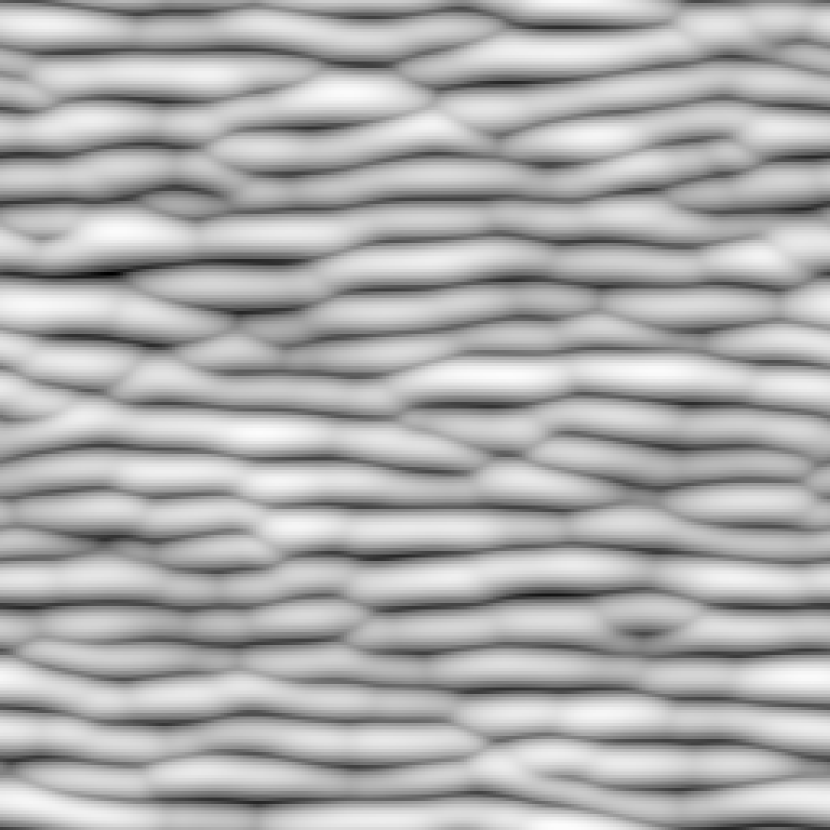
(e)
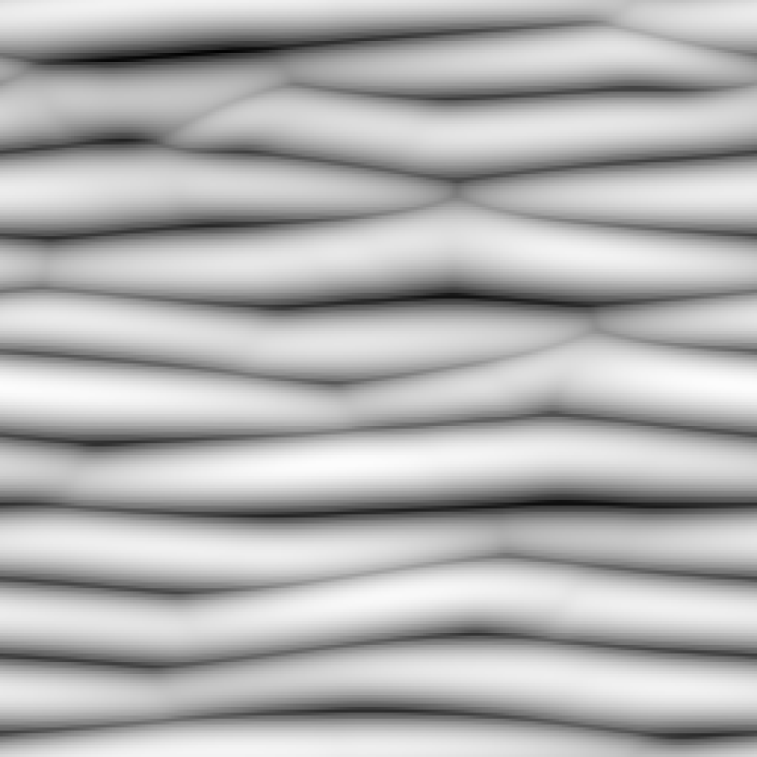
(f)
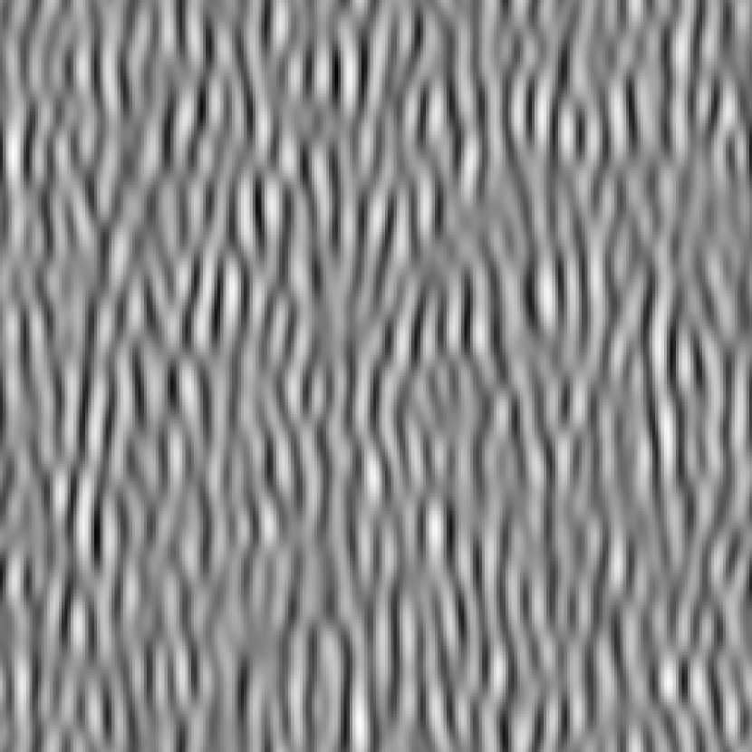
(g)
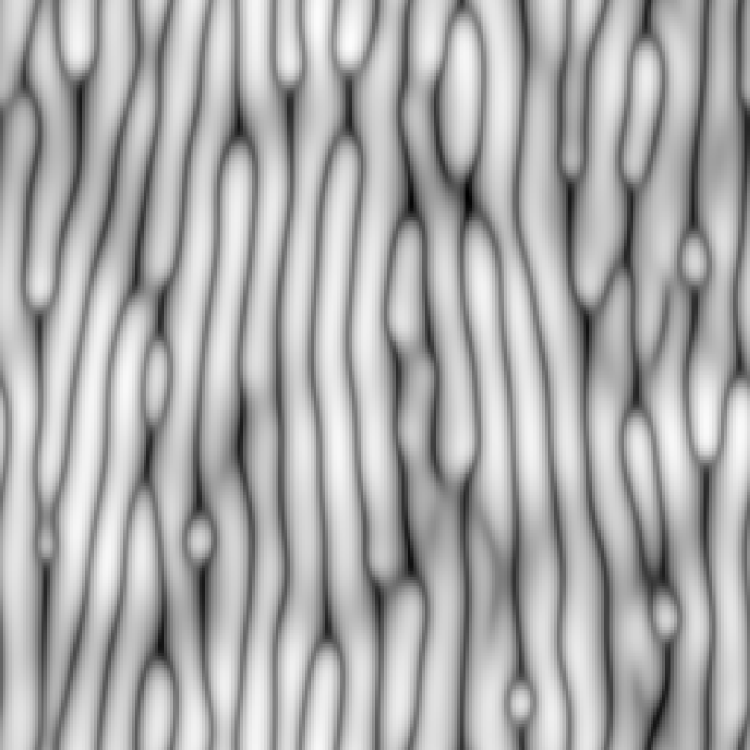
(h)
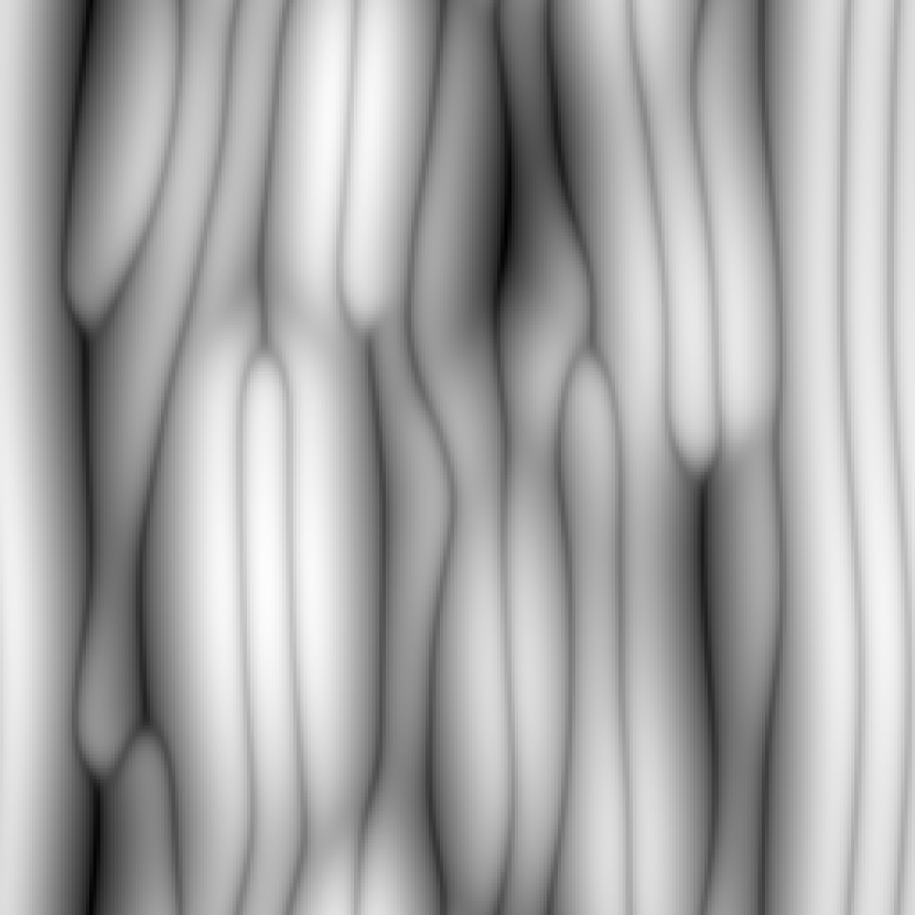
(i)
Top views of the morphologies described by Eq. (4.3) at different times are shown in Fig. 24 for different values of the parameters. In all these examples, the ripples are increasing their size in the course of time while disordering in heights for long distances, whereas the form of the ripples can vary appreciably depending on parameter values. In some cases, as in the first and third rows of Fig. 24, the ripples are disordered longitudinally, whereas in the second row, the ripples are longer and more straight. In the third row, the ripples are also very disordered in height and tend to group themselves in domains which contain, approximately, three ripples each. The ripple coarsening seen in Fig. 24 actually requires the presence of , whose magnitude and mathematically correct sign are due to describing redeposition by means of the additional field . When the values of these coefficients increase relative to , coarsening stops later, and the amplitude and wavelength of the pattern also increase, analogous to the result for one-dimensional interfaces studied in Munoz_2006b . The coarsening exponent will take an effective value that will be larger the later coarsening stops, and may depend on (simulation) parameter values Munoz_2005 .
Asymmetry and transverse in-plane motion of the pattern depends on terms with an odd number of derivatives in Eq. (4.3). Whereas the linear terms tend to make the ripples move with a constant velocity, the nonlinear term accounts for non-uniform movement of the ripples as observed in some experiments Habenicht_2002 ; Alkemade_2006 . In Fig. 25 we show the evolution of a transversal section of the surface as described by Eq. (4.3), where the non-uniform movement and the asymmetry of ripples can be appreciated

An example of a comparison of Eq. (4.3) with experiments is shown in figure 26 where coarsening of the ripples is clearly appreciated. As we see, Eq. (4.3) indeed captures essential properties of the evolution of the experimental topography.
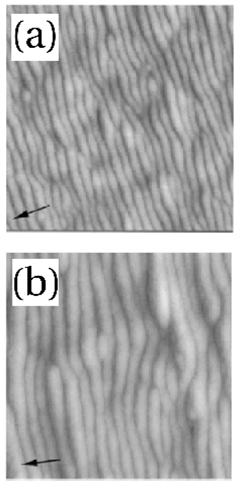
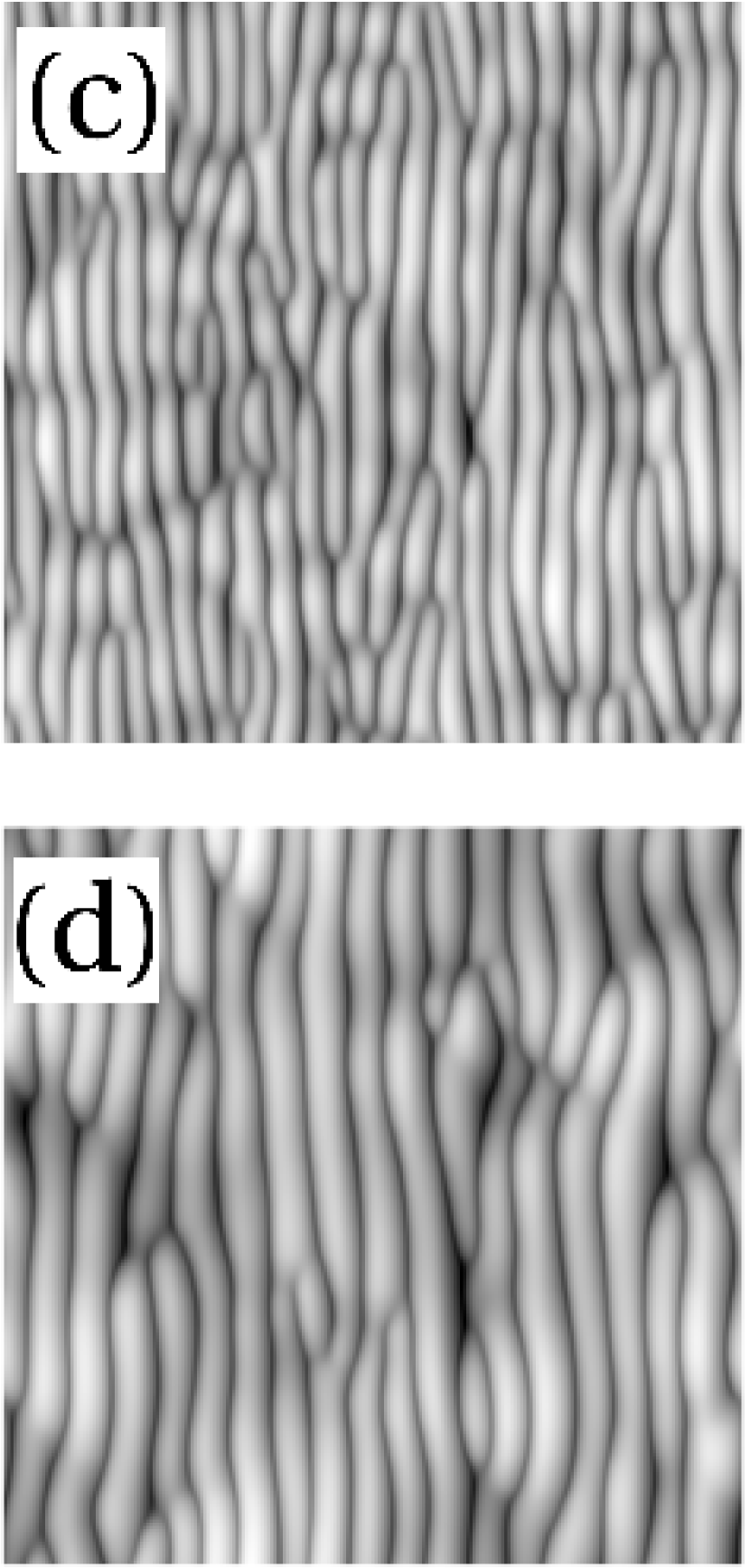
Normal incidence
In the case that the surface is bombarded perpendicularly, the in-plane asymmetry introduced by the oblique beam disappears and, for materials that do not show crystallographically privileged directions, the height equation which describes the evolution of reads Castro_2005 ; Munoz_2005
| (27) |
where, again, the coefficients are related to the Sigmund’s parameters. A stochastic generalization of this equation has been also proposed in the context of amorphous thin film growth Raible_2000 ; Raible_2001 .
An important property of (27) is that, in the absence of redeposited material (), and have the same signs, precisely as occurred in the case of the purely erosive approach Kim_2004 discussed in the previous section. This makes Eq. (27) nonlinearly unstable Raible_2001 ; Castro_2005b . Hence, the description with a single height field seems to feature an intrinsic problem which is solved, if a fraction of redeposited material is large enough, through the two-field “hydrodynamic” approach.
In order to reduce the number of parameters and simplify the analysis of (27), we rescale and , , and by and , respectively, resulting into a single-parameter equation as done in the one-dimensional counterpart of (27) studied in Munoz_2006b . This reads
| (28) |
where is a positive parameter which allows us to perform a numerical analysis of the complete parameter space of Eq. (27) through an appropriate rescaling.
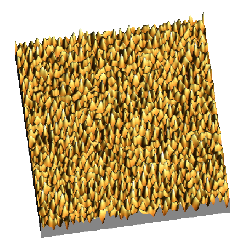
(a)
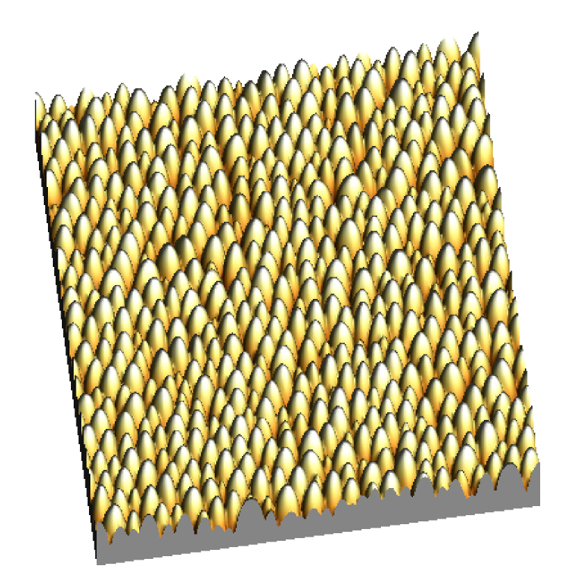
(b)
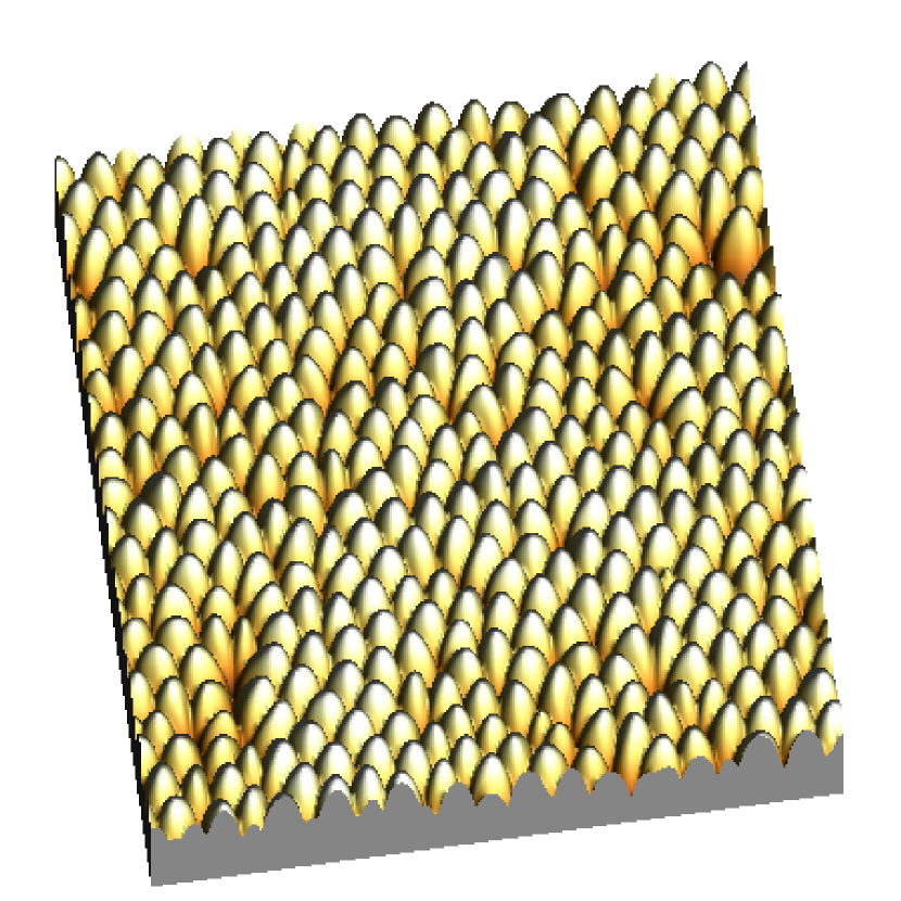
(c)
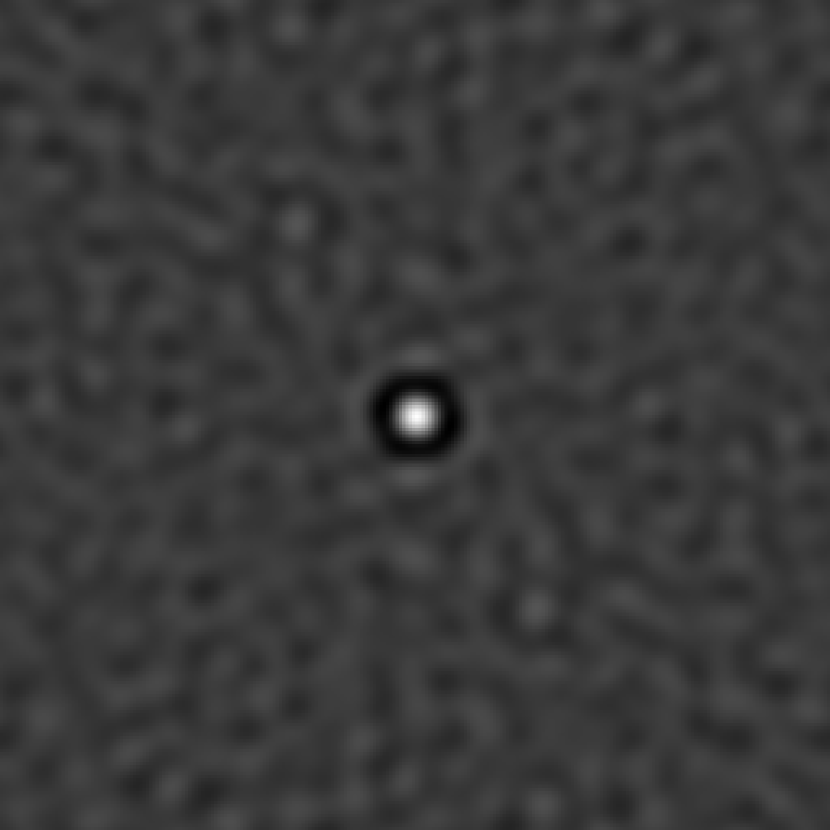
(a)

(b)
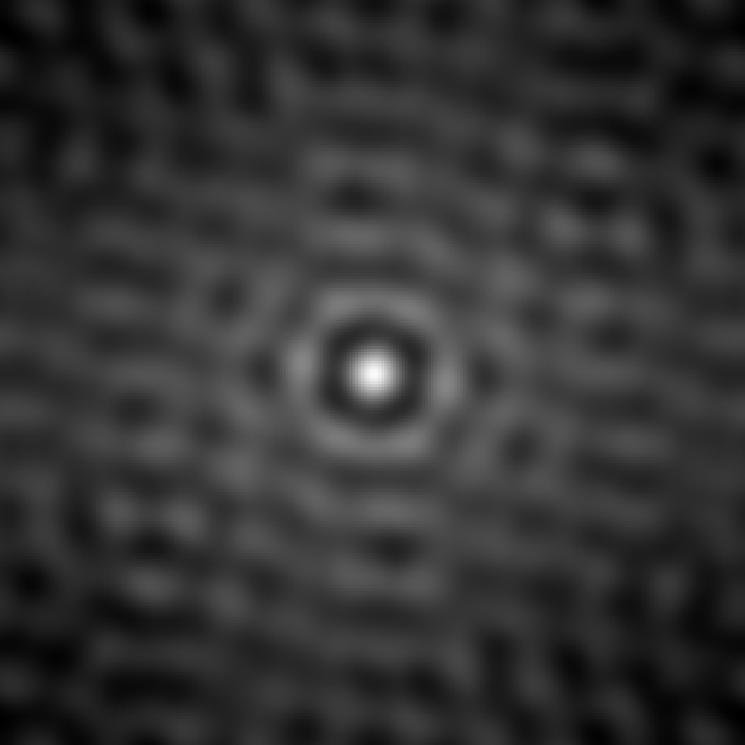
(c)
In Figs. 27 and 28 the evolution of the height profile and corresponding auto-correlation functions are shown for . Starting from an initial random distribution, a periodic surface structure with a wavelength of about the maximum of the linear dispersion relation arises and the amplitude of increases. Then, a coarsening process occurs and dots grow in width and height, the total number of them decreasing. The apparent coarsening is quantified in the plot of shown in Fig. 29 where the saturation of ripple wavelength at long times can be observed. Simultaneously, with dot coarsening, the pattern increase its in-plane order and eventually leading to an hexagonal dot array as shown in Fig. 28.
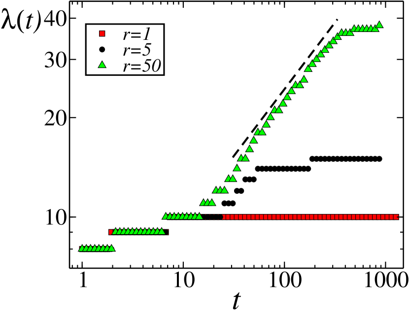
As an example of comparison of this equation with specific experiments, in this paragraph we show the results recently obtained in Gago_2006 where an array of nanodots is obtained over a silicon substrate. In this work, the time evolution of nanodots is considered on Si(001) and Si(111) targets irradiated at normal incidence with Ar+ ions of 1.2 keV. In figures 30 are shown characteristic AFM images of Si(001) and Si(111) surfaces eroded at different times. The pattern is similar in both experiments: in both cases dots of 5-7 nm height and 40-60 nm width are formed and group into short-range hexagonal order. For times larger than 20 minutes, the surface disorders in heights for larger distances (of the order of 6 nm in height and about 500 nm of lateral distance). This long-range disorder (kinetic roughening) increases in the course of the time. In this experiment, the rate of erosion was determined experimentally in all the processed samples by partially masking them during the sputtering process and measuring the resulting step edge height with a profilometer. It was observed that the sputtering rate (SR) was higher for Si(111) than for Si(001). In order to understand the differences found experimentally between the two surface orientations, we have integrated Eq. (27) numerically considering this fact. Thus, as the model neglects target crystallinity, we have used this relative difference in SR to simulate the IBS pattern evolution in two model systems. Insets of Figs. 30(a) and 30(b) display the two-dimensional 2D top-view images from the simulations for surfaces with a given SR at two different simulation times (time and length units are arbitrary). Similarly, insets of Figs. 30(c) and 30(d) correspond to the same simulations for a surface with a higher SR, thus representing the Si(111) orientation. The simulations reproduce in both cases the experimental coarsening and occurrence of a long-wavelength corrugation. In order to quantify the pattern features, the PSD functions corresponding to simulations were systematically analyzed. In Fig. 9 is shown that the pattern wavelength saturates earlier for the surface with higher SR, but the lower SR case attains a larger final dot size. In addition, it is also shown that the correlation length also saturates earlier for a higher SR surface. Remarkably, both AFM and simulation results agree in estimating ordered domains to contain roughly three nanodots. This agreement between simulations and experimental observations allows us to conclude e.g. that the experimental differences observed between the pattern evolution on Si(111) and Si(001) surfaces are due to their different SRs.
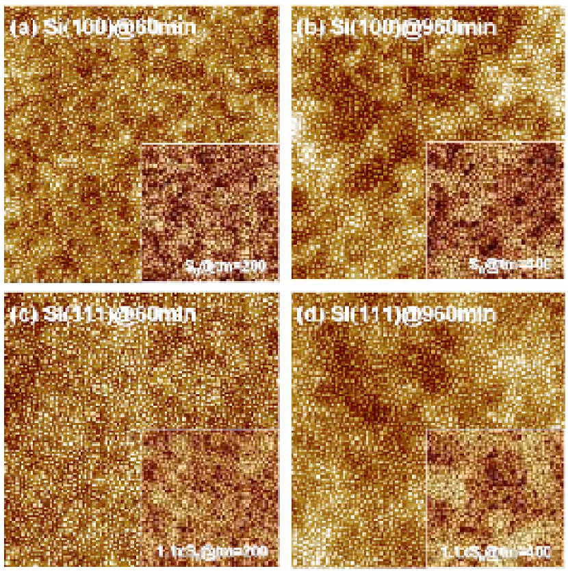
Rotating substrate
Following the ideas of Ref. Bradley_1996 , in Ref. Munoz_2005 we obtained the evolution equation for the surface in case the substrate is rotating simultaneously while bombarding. This reads
| (29) |
where a relationship between these parameters and those in Eq. (4.3) exists.
Preliminar simulations of Eq. (29) Munoz_2007 show that this equation also presents interrupted coarsening and an ordered array of dots, in which the effect in the morphology evolution of the new term is similar to that of .
Comparison between continuum models
The continuum description of nanopattern formation by IBS is currently still open and making progress. As seen in this Section, to date there are several alternative descriptions available that share some of their predictions, while differing in several other aspects. It is also true that theoretical work is not even complete yet —in terms of analyzing systematically the dependences of morphological properties with physical parameters such as e.g. temperature or ion energy— due to two main reasons: (i) the main interfacial equations are nonlinear, thus not easily amenable to analytical solutions, while some of the physically interesting features such as the stationary pattern wavelength depend crucially on non-linear effects; (ii) the parameter spaces of these models are frequently large, particularly in the oblique-incidence case. Actually, some of the interface equations that we have been considering seem to be new in the wider contexts of Non-equilibrium Systems and Non-linear Dynamics Munoz_2006b ; Castro_2007 ; Cuerno_2007 even to the extent of providing examples of thus far unknown behaviors for problems of high current interest, such as coarsening phenomena Politi_2006 .
As a partial summary, and for the sake of comparison, we have collected in table 3 the main available morphological predictions of the models that we have considered in a larger detail in the text. After comparison with the analogous experimental tables 1 and 2, the two-field model leading to Eqs. (4.3), (27) and (29) seems to date the theoretical description that can account for a larger range of experimental behaviors from within a single framework. Naturally, more work is still needed in order to reach a still more complete description of these physical systems with a larger quantitative predictive power.
| NM | ||||
| In-plane order | Disordered | Disordered | Hexagonal | Hexagonal |
| Uniform | Non-uniform | Uniform | Non-uniform | |
| Kinetic roughening | NM | Yes | No | Yes |
5 Applications of IBS patterned surfaces
As mentioned in the Introduction, surface nanopatterning is the subject of intense research driven by the current road to miniaturization and the broad range of eventual applications. Therefore, the formation of self-organized patterns on surfaces by IBS is relevant from a fundamental point of view but also from a practical point of view. Whereas the understanding of the patterning process has been studied deeply from the theoretical and experimental points of view, the applications of these patters have been scarcely addressed and a further technological effort is required for their implementation in real devices. Here, we summarize some of the applications launched in the literature.
One of the strengths of the IBS nanopatterning process comes from its universality since, as shown in section 3, it is applicable to metallic, semiconducting or insulating surfaces. However, in comparison with other techniques, the major advantages of this technique rely on its simplicity, high output (fast) and scalable patterned area. Among the pattern characteristics, we can highlight the tunable wavelength and presence of ordering.
The first applications of IBS patterns were based on the production of micro-scale ripple patterns. In this case, the usage of these patterns for optical interference gratings was addressed Johnson_1979 . Recently, optical activation of the surface due to the pattern formation has also been reported Mussi_2006 which, apart from the surface morphology, may be also linked directly to the ion induced defects.
Perhaps the most important and direct application of IBS patterning relies with the method based on the deposition of a given material layer on top of the target material intended to be patterned. This layer is then ion sputtered, this process inducing a nanopattern on top of it that, by continuing the sputtering process, is eventually transferred onto the target substrate. This strategy was previously used to generate a Ni dot pattern with a typical wavelength of 250-300 nm and dot height of 13-15 nm Seoo_2004 . In this case, the top-layer was a copolymer with self-organized polymer domains. These domains did show different sputtering rates when ion sputtered. In this case, these Ni nanopatterns were used to separate DNA molecules.
The interest on IBS patterns was greatly increased by the report of nanodot pattern formation by Facsko et al. Facsko_1999 as the distances involved were clearly in the nanometer range. Therefore, the potential application for quantum dot (QD) arrays fabrication Facsko_2000 triggered further research. This route for QD fabrication is shown schematically in Fig. 31 and was experimentally proved by the successful photoemission of confined nanostructures Facsko_1999 . Despite this result, there are issues to be improved for the final applicability, such as the crystallinity of the nanostructures, since ion bombardment induces considerable amorphization on the surface. This constraint may not play a big role if the nanodot volume is mostly crystalline. In any case, re-crystallization or damage reduction may be attained by post-annealing treatments.
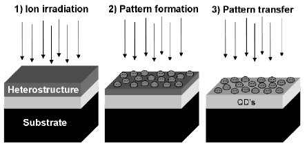
The IBS patterns can be also used as molds or masters to transfer or replicate the pattern to other surfaces with high functionality. This several-step process may be required when the surface can not be processed directly, such as the case of polymer materials, or if the desired pattern can not be obtained in a simple way (for example, when the diffusive regime is operating in metals). Also, this imprinting path may be interesting for reducing production costs by faster processing or avoiding the use of vacuum environments. The applicability of IBS patterned surfaces for molding and replication has been shown by Azzaroni et al. Azzaroni_2003 in polymer materials but the method has been successfully extended to metals Azzaroni_2004b and even hard ceramic materials Auger_2005 . The replication method is shown schematically in Fig. 32a and consists of several sequential steps: (1) production of the IBS dot pattern on a silicon surface; (2) formation of a self-assembled monolayer of octadecyltrichlorosilane (OTS) on top of the nanostructured surface; (3) subsequent growth of the material to be patterned. This step has to be performed at mild conditions (i.e, low temperatures or under non-high energetic sputtering conditions) in order to preserve the OTS layer; (4) thanks to the antisticking properties of the OTS layer the film deposited on top of it can be easily mechanically detached. Also, due to the extremely low thickness of the OTS layer the film surface in contact with it follows the surface morphology of the underlying nanostructured surface. Thus, the surface morphology of the detached film is the negative of the IBS nanostructured silicon surface. In Fig. 32b we show the molded surface of a diamond-like carbon (DLC) film grown by radio frequency sputtering following this method. The negative hole structure of the IBS dot surface is observed while the two-dimensional auto-correlation function (inset) shows that the short-range hexagonal order is still preserved.
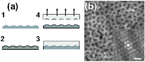
Apart from the direct exploitation of the properties induced in nanopatterned surfaces, much effort has also been devoted to the use of these surfaces as templates for further processing. For example, ripple patterns have been tested as substrates for alignment and manipulation of carbon nanotubes Granone_2005 . In this sense, one possible application would be to extend FIB patterning as a template technique for patterned growth of carbon nanotubes Chen_2007 to IBS nanopatterning. Also, the large range of surface roughness and characteristic wavelengths that are attainable by IBS patterns open a broad field of bioapplications. For example, surface adhesion of biological entities (proteins, DNA, ) may be controlled for sensing, diagnostic or biocompatiability enhancement. Moreover, the nanopit patterns could find applications as supports for catalysis Schildenberger_2000 . Another potential application of IBS patterns is for the production of magnetic nanostructures Terris_2005 . Moroni and coworkers proved that the formation of nanoscale ripples by IBS on Co films deeply affect their magnetic properties Moroni_2003 . Also, IBS patterns have been used as growth templates for the production of magnetic nanostructures. For example, it is well known that the magnetic properties of a superlattice formed by magnetic materials depend on the final thickness of the stack. Therefore, irregularities in the thickness due to non conformal growth, i.e. preferential growth on the cavities (ripples or holes) or on the top of the hills, onto a patterned surface can be used to define magnetic domains Chen_2002 . Another proposal is the use of the surface topography to induce shadowed deposition under oblique precursors incidence Teichert_2003 . These routes are displayed schematically in Fig. 33.
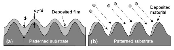
Obviously, the use of patterned surfaces for many applications is not restricted to IBS patterns. However, the presence of the, mostly undesirable, amorphous layer is a peculiarity of IBS patterns that can be used for further applications. For example, the modulation of the amorphous layer in medium-energy induced ripples was very successfully exploited by Smirnov et al. Smirnov_2003 as selective doping implantation barrier. In this case, the production of ripples on silicon by nitrogen erosion leads to the formation of amorphous silicon nitride (SiNx) regions, as shown in Fig. 34. The different nitride layer thicknesses can be used to obtain silicon regions with different degree of doping through, for instance, reactive ion-etching and As+ implantation processes.
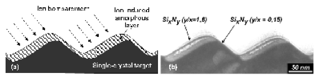
6 Open issues
Despite the large amount of theoretical and experimental work described above, there are still issues that remain unclear and require further research efforts. From the experimental point of view, this is especially evident for the case of nanodot patterns due to their relative novelty. For the case of nanoripples, in spite of the abundant avaliable data, there are also gaps to be filled. Perhaps, the least systematically investigated aspects concern transverse ripple propagation and the relevance of shadowing effects on the morphological evolution. The former is difficult to address due to its evident experimental complexity since in-situ, real time monitoring of the ripple morphology has to be carried out. The second issue, although quite specific, is interesting because it can provide important data for theory refinement, which requires exploring systematically the continuum models beyond the customary small-slope approximation. With regard to nanodot patterns, there is still a certain lack of systematicity in the studies of the various targets that have proved amenable to such patterns when subject to IBS. For instance, the role of preferential sputtering on nanostructuring of hetero-semiconductors has not been unambiguously assessed yet. In addition, the effect of temperature on the nanodot morphology or the symmetry of their arrangement is not clear as different, and in some cases opposite, behaviors have been found. Another issue that will be interesting to address will be the systematic comparison of the nanodot pattern properties for the same target material bombarded under normal incidence and under oblique incidence with simultaneous target rotation. In this sense, comparison is still incomplete between the IBS patterns produced with the same equipment on different materials. A related open issue is the influence of the characteristics of the ion gun optics on the pattern properties.
Another line of research with important implications in the theoretical understanding of IBS patterning is that of pattern coarsening. From the data compiled, it is clear that many systems present coarsening but also there are others that do not. Thus, an important experimental investigation would be the study of the physical processes behind pattern coarsening. Once more, the results of these investigations would contribute to improving the theoretical models and hence deepen our understanding of IBS patterning formation. In this connection, an ambitious goal is to clarify the relationship between the more relevant parameters appearing in the continuum models with the specific properties of the target materials and ion species. This research would indeed help to understand quantitatively the different patterns properties found experimentally, such as for instance the different size and shape of dots found in Si, GaSb and InP. Moreover, it would be interesting to design specific experiments in order to verify alternative predictions from the various models. An example of this can be the experimental verification of recent proposals to produce novel nanopatterns under specific multi-beam irradiation conditions Carter_2004 ; Carter_2005 ; Carter_2006 .
Finally, from a more applied point of view, the use of IBS nanostructuring processes for technological applications remains as an important challenge since, although several specific applications have been already developed, they have not yet proved clear advantages with respect to previously existing alternative routes.
Acknowledgements
We are pleased to acknowledge collaborations and exchange with a number of colleagues, in particular JM Albella, MC Ballesteros, A-L Barabási, M Camero, T Chini, M Feix, AK Hartmann, R Kree, M Makeev, TH Metzger, O Plantevin, M Varela and EO Yewande. We would like to thank specially F Alonso for his help in the ripple experiments on Si at 40 keV shown in Sec. 3.
Our work has been partially supported by Spanish grants Nos. FIS2006-12253-C06 (-01, -02, -03, -06) from Ministerio de Educación y Ciencia (MEC), CCG06-UAM/MAT-0040 from Comunidad Autónoma de Madrid (CAM) and Universidad Autónoma de Madrid, UC3M-FI-05-007 and CCG06-UC3M/ESP-0668 from CAM and Universidad Carlos III de Madrid, and S-0505/ESP-0158 from CAM, and by the Ramón y Cajal programme of MEC (RG).
References
- (1) Alkemade PFA, Jiang ZX (2001) Complex roughening of Si under oblique bombardment by low-energy oxygen ions. J Vac Sci Technol 19: 1699-1705
- (2) Alkemade PFA (2006) Propulsion of ripples on glass by ion bombardment. Phys Rev Lett 96: 107602
- (3) Amirtharaj PM, Little J, Wood GL, Wickenden A, Smith DD (2002) The army pushes the boundary of sensor performance through nanotechnology. In Grethlein CE (ed) The AMPTIAC Newsletter, Spring 2002, Special Issue: Nanotechnology 6: 49-56
- (4) Andersen HH, Bay HL (1981) Sputtering by particle bombardment vol I Chapter 4: R. Behrisch (Ed.). Springer, Berlin, pp 145-218
- (5) Auger MA, Schilardi PL, Caretti I, Sánchez O, Benítez G, Albella JM, Gago R, Fonticelli M, Vázquez L, Salvarezza RC, Azzaroni O (2005) Molding and Replication of Ceramic Surfaces with Nanoscale Resolution. Small 1: 300-309
- (6) Aste T, Valbusa U (2004) Surface instabilities in granular matter and ionsputtered surfaces. Physica A 332: 548-558
- (7) Aste T, Valbusa U (2005) Ripples and ripples: from sandy deserts to ionsputtered surfaces. New J Phys 7: 122
- (8) Azzaroni O, Schilardi PL, Salvarezza RC, Gago R, Vázquez L (2003) Direct molding of nanopatterned polymeric films: Resolution and errors. Appl Phys Lett 82: 457-459
- (9) Azzaroni O, Fonticelli MH, Benítez G, Schilardi PL, Gago R, Caretti I, Váquez L, Salvarezza RC (2004) Direct nanopatterning of metal surfaces using self-assembled molecular films. Adv Mater 16: 405-409
- (10) Azzaroni O, Fonticelli M, Schilardi PL, Benítez G, Caretti I, Albella JM, Gago R, Vázquez L, Salvarezza RC (2004) Surface nanopatterning of metal thin films by physical vapour deposition onto surface-modified silicon nanodots. Nanotechnol 15: S197-S200
- (11) Binnig G, Quate C, Gerber Ch (1986) Atomic force microscope. Phys Rev Lett 56: 930-933
- (12) Bobek T, Facsko S, Kurz H, Xu M, Teichert C (2003) Temporal evolution of dot patterns during ion sputtering. Phys Rev B 68: 085324
- (13) Bradley RM, Harper JME (1988) Theory of ripple topography induced by ion-bombardment. J Vac Sci Technol A 6: 2390-2395
- (14) Bradley RM (1996) Dynamic scaling of ion-sputtered rotating surfaces. Phys Rev E 54: 6149-6152
- (15) Bringa EM, Johnson RE, Papal o RM (2002) Crater formation by single ions in the electronic stopping regime: Comparison of molecular dynamics simulations with experiments on organic films. Phys Rev. B 65: 094113
- (16) Brown AD, Erlebacher J (2005) Temperature and fluence effects on the evolution of regular surface morphologies on ion-sputtered Si(111). Phys Rev B 72: 075350
- (17) Brown AD, Erlebacher J (2005) Transient topographies of ion patterned Si(111). Phys Rev Lett 95: 056101
- (18) Calleja M, Anguita J, García R, Birkelund K, Pérez-Murano F, Dagata JA (1999) Nanometer-scale oxidation of silicon surfaces by dynamic force microscopy: Reproducibility, kinetics and nanofabrication. Nanotechnol 10: 10044-10050
- (19) Carter G, Vishnyakov V (1996) Roughening and ripple instabilities on ion-bombarded Si. Phys Rev B 54: 17647-17653
- (20) Carter G (1999) The effects of surface ripples on sputtering erosion rates and secondary ion emission yields. J Appl Phys 85: 455-459
- (21) Carter G (2001) The physics and applications of ion beam erosion. J Phys D Appl Phys 34: R1-R22
- (22) Carter G (2004) Proposals for producing novel periodic structures by ion bombardment sputtering. Vacuum 77: 97-100
- (23) Carter G (2005) Surface ripple amplification and attenuation by sputtering with diametrically opposed ion fluxes. Vacuum 79: 106-109
- (24) Carter G (2006) Proposals for producing novel periodic structures on silicon by ion bombardment sputtering. Vacuum 81: 138-140
- (25) Castro M, Cuerno R, Vázquez L, Gago R (2005) Self-organized ordering of nanostructures produced by ion-beam sputtering. Phys Rev Lett 94: 016102
- (26) Castro M, Cuerno R (2005) Comment on “Kinetic roughening of ion-sputtered Pd(001) surface: beyond the Kuramoto-Sivashinsky model”. Phys Rev Lett 94: 139601
- (27) Castro M, Muñoz-García J, Cuerno R, García-Hernández M, Vázquez L (2007) Generic equations for pattern formation in evolving interfaces. New J Phys in press
- (28) Chason E, Mayer TM, Kellerman BK, McIlroy DT, Howard AJ (1994) Roughening instability and evolution of the Ge(001) surface during ion sputtering. Phys Rev Lett 72: 3040-3043
- (29) Chason E, Kellerman BK (1997) Monte Carlo simulations of ion-enhanced island coarsening. Nucl Instrum Methods Phys Res B 127: 225-229
- (30) Chason E, Erlebacher J, Aziz MJ, Floro JA, Sinclair MB (2001) Dynamics of pattern formation during low-energy ion bombardment of Si(001). Nucl Instr and Meth B 178: 55-61
- (31) Chason E, Chan WL (2006) Kinetic mechanisms in ion-induced ripple formation on Cu(001) surfaces. Nucl. Instrum. Methods Phys Res B 242: 232-236
- (32) Chason E, Chan WL, Bharathi MS (2006) Kinetic Monte Carlo simulations of ion-induced ripple formation: Dependence on flux, temperature, and defect concentration in the linear regime. Phys Rev B 74: 224103
- (33) Chen YJ, Wilson IH, Cheung WY, Xu JB, Wong SP (1997) Ion implanted nanostructures on Ge(111) surfaces observed by atomic force microscopy. J Vac Sci Technol B 15: 809-813
- (34) Chen YJ, Wang JP, Soo EW, Wu L, Chong TC (2002) Periodic magnetic nanostructures on self-assembled surfaces by ion beam bombardment. J Appl Phys 91: 7323-7184
- (35) Chen HH, Orquidez OA, Ichim S, Rodriguez LH, Brenner MP, Aziz MJ (2005) Shocks in ion sputtering sharpen steep surface features. Science 310: 294-297
- (36) Chen Y, Chen H, Yu J, Williams JS, Craig V (2007) Focused ion beam milling as a universal template technique for patterned growth of carbon nanotubes. Appl Phys Lett 90: 093126
- (37) Chey SJ, Van Nostrand JE, Cahill DG (1995) Surface morphology of Ge(001) during etching by low-energy ions. Phys Rev B 52: 16696-166701
- (38) Chini TK, Sanyal MK, Bhattacharyya SR (2002) Energy-dependent wavelength of the ion-induced nanoscale ripple. Phys Rev B 66: 153404
- (39) Chini TK, Okuyama F, Tanemura M, Nordlund K (2003) Structural investigation of keV Ar-ion-induced surface ripples in Si by cross-sectional transmission electron microscopy. Phys Rev B 67: 205403
- (40) Cirlin E-H, Vajo JJ, Doty RE, Hasenberg TC (1991) Ion-induced topography, depth resolution, and ion yield during secondary ion mass spectrometry depth profilling of GaAs/AlGaAs superlattice: effects of sample rotation. J Vac Sci Technol A 9: 1395
- (41) Costantini G, de Mongeot FB, Boragno C, Valbusa U (2001) Is ion sputtering always a “negative homoepitaxial deposition”?. Phys Rev Lett 86: 838-841
- (42) Csahók Z, Misbah C, Rioual F, Valance A (2000) Dynamics of aeolian sand ripples. Eur Phys J E 3: 71-86
- (43) Cuenat A, Aziz MJ (2002) Spontaneous pattern formation from focused and unfocused ion beam irradiation. Mat Res Soc Symp Proc 696: N2.8.1-N.2.8.6
- (44) Cuerno R, Barabási AL (1995) Dynamic scaling of ion-sputtered surfaces. Phys Rev Lett 74: 4746-4749
- (45) Cuerno R, Makse HA, Tomassone S, Harrington ST, Stanley HE (1995) Stochastic Model for Surface Erosion via Ion Sputtering: Dynamical Evolution from Ripple Morphology to Rough Morphology. Phys Rev Lett 75: 4464-4467
- (46) Cuerno R, Castro M, Muñoz-García J, Gago R, Vázquez L (2007) Universal non-equilibrium phenomena at submicrometric surfaces and interfaces. Eur Phys J Special Topics. In press
- (47) Datta A, Wu YR, Wang YL (2001) Real-time observation of ripple structure formation on a diamond surface under focused ion-beam bombardment. Phys Rev B 63: 125407
- (48) Datta D, Bhattacharyya SR, Chini TK, Sanyal MK (2002) Evolution of surface morphology of ion sputtered GaAs(100). Nucl Instr and Meth B 193: 596-602
- (49) Datta DP, Chini TK (2004) Atomic force microscopy study of 60-keV Ar-ion-induced ripple patterns on Si(100). Phys Rev B 69: 235313
- (50) Datta DP, Chini TK (2005) Spatial distribution of Ar on the Ar-ion-induced rippled surface of Si. Phys Rev B 71: 235308
- (51) Demanet CV, Malherbe JB, van der Berg NG, Sankar V (1995) Atomic force microscopy investigation of argon-bombarded InP: Effect of ion dose density. Surf Interface Anal 23: 433-439
- (52) Diaz de la Rubia T, Averback RS, Benedeck R, King WE (1987) Role of thermal spikes in energetic displacement cascades. Phys Rev Lett 59: 1930-1933
- (53) Erlebacher J, Aziz MJ, Chason E, Sinclair MB, Floro JA (1999) Spontaneous pattern formation on ion bombarded Si(001). Phys Rev Lett 82: 2330-2333
- (54) Ehrlich G, Hudda FG (1966) Atomic view of surface self-diffusion: Tungsten on tungsten. J Chem Phys 44: 1039-1049
- (55) Facsko S, Dekorsy T, Koerdt C, Trappe C, Kurz H, Vogt A, Hartnagel HL (1999) Formation of ordered nanoscale semiconductor dots by ion sputtering. Science 285: 1551-1553
- (56) Facsko S, Dekorsy T, Trappe C, Kurz H (2000) Self-organized quantum dot formation by ion sputtering. Microelectron Eng 53: 245-248
- (57) Facsko S, Kurz H, Dekorsy T (2001) Energy dependence of quantum dot formation by ion sputtering. Phys Rev B 63: 165329
- (58) Facsko S, Bobek T, Kurz H, Dekorsy T, Kyrsta S, Cremer R (2001) Ion-induced formation of regular nanostructures on amorphous GaSb surfaces. Appl Phys Lett 80: 130-132
- (59) Facsko S, Bobek T, Stahl A, Kurz H, Dekorsy T (2004) Dissipative continuum model for self-organized pattern formation during ion-beam erosion. Phys Rev B 69: 153412
- (60) Fan WB, Li WQ, Qi LJ, Sun HT, Luo J, Zhao YY, Lu M (2005) On the role of ion flux in nanostructuring by ion sputter erosion. Nanotechnol 16: 1526-1529
- (61) Feix M, Hartmann AK, Kree R, Muñoz-García J, Cuerno R (2005) Influence of collision cascade statistics on pattern formation of ion-sputtered surfaces. Phys Rev B 71: 125407
- (62) Finnine I (1995) Some reflections on the past and future of erosion. Wear 186-187: 1-10
- (63) Flamm D, Frost F, Hirsch D (2001) Evolution of surface topography of fused silica by ion beam sputtering. Appl Surf Sci 179: 95-101
- (64) Frost F, Schindler A, Bigl F (2000) Roughness evolution of ion sputtered rotating InP surfaces: Pattern formation and scaling laws. Phys Rev Lett 85: 4116-4119
- (65) Frost F, Hirsch D, Schindler A (2001) Evaluation of AFM tips using nanometer-sized structures induced by ion sputtering. Appl Surf Sci 179: 8-12
- (66) Frost F, Rauschenbach B (2003) Nanostructuring of solid surfaces by ion-beam erosion. Appl Phys A 77: 1-9
- (67) Frost F, Fechner R, Ziberi B, Flamm D, Schindler A (2004) Large area smoothing of optical surfaces by low-energy ion beams. Thin Sol Films 459: 100-1005.
- (68) Frost F, Ziberi B, Höche T, Rauschenbach B (2004) The shape and ordering of self-organized nanostructures by ion sputtering. Nucl Instr and Meth B 216: 9-19
- (69) Frost F, Fechner R, Flamm D, Ziberi B, Frank W, Schindler A (2004) Ion beam assisted smoothing of optical surfaces. Appl Phys A 78: 651-654
- (70) Gago R, Vázquez L, Cuerno R, Varela M, Ballesteros C, Albella JM (2001) Production of ordered silicon nanocrystals by low-energy ion sputtering. Appl Phys Lett 78: 3316-3318
- (71) Gago R, Vázquez L, Cuerno R, Varela M, Ballesteros C, Albella JM (2002) Nanopatterning of silicon surfaces by low-energy ion-beam sputtering: Dependence on the angle of ion incidence. Nanotechnol 13: 304-308
- (72) Gago R, Vázquez L, Plantevin O, Metzger TH, Muñoz-García J, Cuerno R, Castro M (2006) Order enhancement and coarsening of self- organized silicon nanodot patterns induced by ion-beam sputtering. Appl Phys Lett 89: 233101
- (73) Gago R, Vázquez L, Sánchez-García JA, Varela M Ballesteros MC, Plantevin O, Albella JM, Metzger TH (2006) Temperature influence on the production of nanodot patterns by ion beam sputtering of Si(001). Phys Rev B 73: 155414
- (74) Granone F, Mussi V, Toma A, Orlanducci S, Terranova ML, Boragno C, Buatier de Mongeot F, Valbusa U (2005) Ion sputtered surfaces as templates for carbon nanotubes alignment and deformation. Nucl Inst. and Meth B 230: 545-550
- (75) Grove WR (1852) On the electrochemical polarity of gases. Phil Trans R Soc (London) B 142: 87
- (76) Guo LJ (2007) Nanoimprint lithography: Methods and material requirements. Adv Mater 19: 495-513
- (77) Habenicht S, Bolse W, Lieb KP, Reimann K, Geyer U (1999) Nanometer ripple formation and self-affine roughening of ion-beam-eroded graphite surfaces. Phys Rev B 60: R2200-R2203
- (78) Habenicht S (2001) Morphology of graphite surfaces after ion-beam erosion. Phys Rev B 63: 125419
- (79) Habenicht S, Lieb KP, Koch J, Wieck AD (2002) Ripple propagation and velocity dispersion on ion-beam-eroded silicon surfaces. Phys Rev B 65: 115327
- (80) Harrison DE (1988) Application of molecular-dynamics simulations to the study of ion-bombarded metal-surfaces. Crit Rev Solid State Mater Sci 14: S1-S78.
- (81) Hartmann AK, Kree R, Geyer U, Kölbel M (2002) Long-time effects in a simulation model of sputter erosion. Phys Rev B 65: 193403
- (82) Hazra S, Chini TK, Sanyal MK, Grenzer J, Pietsch U (2004) Ripple structure of crystalline layers in ion-beam-induced Si wafers. Phys Rev B 70: 121307(R)
- (83) Hodes G (2007) When small is different: Some recent advances in concepts and applications of nanoscale phenomena. Adv Mater 19: 639-655
- (84) Hofer C, Abermann S, Teichert C, Bobek T, Kurz H, Lyutovich K, Kasper E (2004) Ion bombardment induced morphology modifications on self-organized semiconductor surfaces. Nucl Inst and Meth B 216: 178-184
- (85) Jeffries JH, Zuo JK, Craig MM (1996) Instability of kinetic roughening in sputter-deposition growth of Pt on glass. Phys Rev Lett 76: 4931-4934
- (86) Johnson LF, Ingersoll KA (1979) Interference gratings blazed by ion-beam erosion. Appl Phys Lett 35: 500-503
- (87) Kahng B, Jeong H, Barábasi AL (2001) Quantum dot and hole formation in sputter erosion. Appl Phys Lett 78: 805-807
- (88) Kardar M, Parisi G, Zhang YC (1986) Dynamic Scaling of growing interfaces. Phys Rev Lett 56: 889-892
- (89) Karen A, Okuno A, Soeda F, Ishitani I (1991) A study of the secondary-ion yield change on the GaAs surface caused by the O ion-beam-induced rippling. J Vac Sci Technol A 9: 2247-2252
- (90) Karmakar P, Ghose D (2004) Ion beam sputtering induced ripple formation in thin metal films. Surf Sci 554: L101-L106
- (91) Karmakar P, Goshe D (2005) Nanoscale periodic and faceted structures formation on Si(100) by oblique angle oxygen ion sputtering. Nucl Instr and Meth B 230: 539-544
- (92) Kasemo B (2002) Biological surface science. Surf Sci 500: 656-677
- (93) Kim J, Cahill DG, Averback RS (2003) Surface morphology of Ge(111) during etching by keV ions. Phys Rev B 67: 045404
- (94) Kim TC, Ghim C-M, Kim HJ, Kim DH, Noh DY, Kim ND, Chung JW, Yang JS, Chang YJ, Noh TW, Kahng B, Kim J-S (2004) Kinetic Roughening of Ion-Sputtered Pd(001) Surface: Beyond the Kuramoto-Sivashinsky Model. Phys Rev Lett 92: 246104
- (95) Kim TC, Ghim C-M, Kim HJ, Kim DH, Noh DY, Kim ND, Chung JW, Yang JS, Chang YJ, Noh TW, Kahng B, Kim J-S (2005) Kim et al. Reply. Phys Rev Lett 94: 139602
- (96) Koponen I, Hautala M, Sievänen O-P (1996) Simulations of submicrometer-scale roughening on ion-bombarded solid surfaces. Phys Rev B 54: 13502-13505
- (97) Koponen I, Hautala M, Sievänen O-P (1997) Simulations of roughening of amorphous carbon surfaces bombarded by low-energy Ar-ions. Nucl Instrum Methods Phys Res B 127-128: 230-234
- (98) Koponen I, Hautala M, Sievänen O-P (1997) Simulations of ripple formation on ion-bombarded solid surfaces. Phys Rev Lett 78: 2612-2615
- (99) Koponen I, Sievänen O-P, Hautala M, Hakovirta M (1997) Simulations of sputtering induced roughening and formation of surface topography in deposition of amorphous diamond films with mass separated kiloelectronvolt ion beams. J Appl Phys 82: 6047-6055
- (100) Koponen I, Hautala M, Sievänen O-P (1997) Simulations of self-affine roughening and ripple formation on ion bombarded amorphous carbon surfaces. Nucl Instrum Methods Phys Res B 129: 349-355
- (101) Krim J, Heyvaert I, Haesendonck CV, Bruynseraede Y (1993) Scanning tunnelling microscopy observation of self-affine fractal roughness in ion-bombarded film surfaces. Phys Rev Lett 70: 57-60
- (102) Krug J (2004) Kinetic pattern formation at solid surfaces. In: Radons G, Häussler P, Just W (eds) Collective dynamics of nonlinear and disordered systems. Springer, Berlin.
- (103) Kulriya PK, Tripathi A, Kabiraj D, Khan SA, Avasthi DA (2006) Study of 1.5 keV Ar atoms beam induced ripple formation on Si surface by atomic force microscopy. Nucl Instr and Meth B 244: 95-99
- (104) Kustner M, Eckstein W, Dose V, Roth J (1998) The influence of surface roughness on the angular dependence of the sputter yield. Nucl Instr and Meth B 145: 320-331
- (105) Lau GS, Tok ES, Liu R, Wee ATS, Tjiu WC, Zhang J (2003) Nanostructure formation by O ion sputtering of Si/SiGe heterostructures. Nanotechnol 14: 1187-1191
- (106) Li YZ, Vázquez L, Piner R, Reifenberger R (1989) Writing nanometer-scale symbols in gold using the scanning tunneling microscope. Appl Phys Lett 54: 1424-1426
- (107) Lindner J, Poulopoulos P, Farle M, Baberschke K (2000) Structure and magnetism of self-organized Ni nanostructures on Cu(001). J Magn Magn Mater 218: 10-16
- (108) Liu ZX, Alkemade PFA (2001) Flux dependence of oxygen-beam- induced ripple growth on silicon. Appl Phys Lett 79: 4334-4336
- (109) Ludwig F Jr, Eddy CR Jr, Malis O, Headrick RL (2002) Si(100) surface morphology evolution during normal-incidence sputtering with 100-500 eV Ar+ ions. Appl Phys Lett 81: 2770-2772
- (110) Maclaren SW, Baker JE, Finnegan WL, Loxton CM (1992) Surface roughness development during sputtering of GaAs and InP: Evidence for the role of surface diffusion in ripple formation and sputter cone development. J Vac Sci Technol A 10: 468-476
- (111) Makeev MA, Barabási AL (1997) Ion-induced effective surface diffusion in ion sputtering. Appl Phys Lett 71: 2800-2802
- (112) Makeev MA, Cuerno R, Barábasi AL (2002) Morphology of ion-sputtered surfaces. Nucl Instr and Meth B 97: 185-227
- (113) Malherbe JB (2003) Bombardment-induced ripple topography on GaAs and InP. Nucl Instr and Meth B 212: 258-263
- (114) Mayer TM, Chason E, Howard AJ (1994) Roughening instability and ion-induced viscous relaxation of SiO2 surfaces. J Appl Phys 73: 1633-1643
- (115) Michely T, Comsa G (1991) Temperature dependence of the sputtering morphology of Pt(111). Surf Sci 256: 217-226
- (116) Mirkin CA (2001) Dip-pen nanolithography: automated fabrication of custom multicomponent, sub-100 nm nanometer surface architectures. MRS Bull 26: 535-538
- (117) Moore DF, Daniel JH, Walker JF (1997) Nano- and micro-technology applications of focused ion beam processing. Microelectron J 28: 465-473
- (118) Mora A, Haase M, Rabbow T, Plath PJ (2005) Discrete model for laser driven etching and microstructuring of metallic surfaces. Phys Rev B 72: 061604
- (119) Mori H, Kuramoto Y (1997) Dissipative structures and chaos. Springer, Berlin
- (120) Moroni R, Sekiba D, Buatier de Mongeot F, Gonella G, Boragno C, Mattera L, Valbusa U (2003) Uniaxial magnetic anisotropy in nanostructured Co/Cu(001): From surface ripples to nanowires. Phys Rev Lett 91: 167207
- (121) Mullins WW (1957) Theory of thermal grooving. J Appl Phys 28: 333
- (122) Mullins WW (1959) Flattening of a nearly plane solid surface due to capillarity J Appl Phys 30: 77
- (123) Muñoz-García J, Castro M, Cuerno R (2006) Nonlinear ripple dynamics on amorphous surfaces patterned by ion beam sputtering. Phys Rev Lett 96: 086101
- (124) Muñoz-García J, Cuerno R, Castro M (2006) Short-range stationary patterns and long-range disorder in an evolution equation for one-dimensional interfaces. Phys Rev E 74: 050103(R)
- (125) Muñoz-García J, Cuerno R, Castro M (2007) In preparation.
- (126) Murty MVR, Cowles B, Cooper BH (1998) Surface smoothing during sputtering: mobile vacancies versus adatom detachment and diffusion. Surf Sci 415: 328-335
- (127) Murty MVR (2002) Sputtering: The material erosion tool. Surf Sci 500: 523-544
- (128) Mussi V, Granonce F, Boragno C, Bautier de Mongeot, Valbusa (2006) Surface nanostructuring and optical activation of lithium fluoride crystals by ion beam irradiation. Appl Phys Lett 88: 103116
- (129) Nastasi MA, Mayer JW, Hirvonen JK (1996) Ion-solid interactions: Fundamentals and applications. Cambridge University Press, New York
- (130) Navez M, Chaperot D, Sella C (1962) Microscopie electronique - etude de l’attaque du verre par bombardement ionique. C R Acad Sci 254: 240-248
- (131) Nord J, Nordlund K, Keinonen J (2003) Molecular dynamics study of damage accumulation in GaN during ion beam irradiation. Phys Rev B 68: 184104
- (132) Oechsner H (1975) Sputtering - Review of some recent experimental and theoretical aspects. Appl Phys 8: 185-198
- (133) Oechsner H (ed.) (1984) Thin film and depth profile analysis. Springer, Berlin.
- (134) Okutani T, Shikate S, Ichimura S, Shimizu R (1980) Angular distribution of Si atoms sputtered by keV Ar+ ions. J Appl Phys 51: 2884-2887
- (135) Ozaydin G, Özcan AS, Wang Y, Ludwig KF, Zhou H, Headrick RL, Siddons DP (2005) Real-time x-ray studies of Mo-seeded Si nanodot formation during ion bombardment. Appl Phys Lett 87: 163104
- (136) Paniconi M, Elder KR (1997) Stationary, dynamical, and chaotic states of the two-dimensional damped Kuramoto-Sivashinsky equation. Phys. Rev. E 56: 2713-2721
- (137) Park S, Kahng B, Jeong H, Barabási AL (1999) Dynamics of ripple formation in sputter erosion: Nonlinear phenomena. Phys Rev Lett 83: 3486-3489
- (138) Plücker J (1958) Observations on the electrical discharge through rarefied gases. The London, Edimburgh and Dublin Phil Mag 16: 409
- (139) Politi P, Misbah C (2006) Nonlinear dynamics in one dimension: A criterion for coarsening and its temporal law. Phys Rev E 73: 036133
- (140) Raible M, Mayr SG, Linz SJ, Moske M, Hänggi P, Samwer K (2000) Amorphous thin-film growth: Theory compared with experiment. Europhys Lett 50: 61-67
- (141) Raible M, Linz SJ, Hänggi P (2001) Amorphous thin film growth: Effects of density inhomogeneities. Phys Rev E 64: 031506
- (142) Rossnagel SM, Robinson RS (1982) Surface diffusion activation energy determination using ion beam microtexturing. J Vac Sci Technol 20: 195-198
- (143) Rossnagel SM (2003) Thin film deposition with physical vapor deposition and related technologies. J Vac Sci Technol A 21: S74-S87
- (144) Rost M, Krug J (2005) Anisotropic Kuramoto-Sivashinsky equation for surface growth and erosion. Phys Rev Lett 75 : 3894-3897
- (145) Roth J (1983) Chemical sputtering. Topics Appl Phys 52: 91-146
- (146) Rusponi S, Boragno C, Valbusa U (1997) Ripple structure on Ag(110) surface induced by ion sputtering. Phys Rev Lett 78: 2795-2798
- (147) Rusponi S, Constantini G, Boragno C, Valbusa U (1998) Ripple wave vector rotation in anisotropic crystal sputtering. Phys Rev Lett 81: 2735-2738
- (148) Schildenberger M, Bonetti YC, Gobrecht J, Prins R (2000) Nano-pits: Supports for heterogeneous model catalysts prepared by interference lithograpy. Top Catal 13: 109-120
- (149) Schubert E, Razek N, Frost F, Schindler A, Rauschenbach B (2005) GaAs surface cleaning by low-energy hydrogen ion bombardment at moderate temperatures. J Appl Phys 97: 23511
- (150) Schwoebel RL, Shipsey EJ (1966) Step motion on crystal surfaces. J Appl Phys 37: 3682-3686
- (151) Seoo YS, Luo H, Samuilov VA, Rafailovic h MH, Sokolov J, Gersappe D, Chu B (2004) DNA Electrophoresis on Nanopatterned Surfaces. Nano Lett 4: 659-664
- (152) Shen J, Kischner J (2002) Tailoring magnetism in artificially structured materials: The new frontier. Surf Sci 500: 300-322
- (153) Sigmund P (1969) Theory of sputtering. I. Sputtering yield of amorphous and polycrystalline targets. Phys Rev 184: 383-416
- (154) Sigmund P (1973) A mechanism of surface micro-roughening by ion bombardment. J Mat Sci 8: 1545-1553
- (155) Soh HT, Guarini KW, Quate CF (2001) Scanning probe lithography. Kluwer, Boston.
- (156) Sohn LL, Willet RL (1995) Fabrication of nanostructures using atomic-force-microscope- based lithography. Appl Phys Lett 67: 1552-1554
- (157) Smirnov VK, Kibalov DS, Krivelevich SA, Lepshin PA, Potapov EV, Yankov RA, Skorupa W, Makarov VV, Danilin AB (1999) Wave-ordered structures formed on SOI wafers by reactive ion beams. Nucl Instr and Meth B 147: 310-315
- (158) Smirnov VK, Kibalov DS, Orlov OM, Graboshinikov VV (2003) Technology for nanoperiodic doping of a metal-oxide-semiconductor field-effect transistor channel using a self-forming wave-ordered structure. Nanotechnol 14: 709-715
- (159) Stangl J, Hol V, Bauer G (2004) Structural properties of self-organized semiconductor nanostructures. Rev Mod Phys 76: 725-783
- (160) Stark J (1908) Zeitsch Elecktrochem 14: 752-756
- (161) Stepanova M, Dew SK (2004) Surface relaxation in ion-etch nanopatterning. Appl Phys Lett 84: 1374-1376
- (162) Stepanova M, Dew SK, Soshnikov IP (2005) Copper nanopattern on SiO2 from sputter etching a Cu/SiO2 interface. Appl Phys Lett 86: 073112
- (163) Stepanova M, Dew SK (2006) Self-organized Cu nanowires on glass and Si substrates from suptter etching Cu/substrate interfaces. J Vac Sci Technol B 24: 592-598
- (164) Strobel M, Heinig K-H, Michely T (2001) Mechanisms of pit coarsening in ion erosion of fcc(111) surfaces: a kinetic 3D lattice Monte-Carlo study. Surf Sci 486: 136-156
- (165) Stuart RV, Wehner GK, Anderson GS (1969) Energy distribution of atoms sputtered from polycrystalline metals. J Appl Phys 40: 803-812
- (166) Tachi S, Okudaira S (1986) Chemical sputtering of silicon by F+, Cl+, and Br+ ions - reactive spot model for reactive ion etching. J Vac Sci Technol B 4: 459-467
- (167) Taglauer E (1990) Surface cleaing using sputtering. Appl Phys A 51: 238-251
- (168) Tan SK, Liu R, Sow CH, Wee ATS (2006) Self-organized nanodot formation on InP(100) by oxygen ion sputtering. Nucl Instr and Meth B 248: 83-89
- (169) Tan SK, Wee ATS (2006) Self-organized nanodot formation on InP(100) by argon ion sputtering at normal incidence. J Vac Sci Technol B 24: 1444-1448
- (170) Teichert C (2001) Self-organization of nanostructures in semiconductor heteroepitaxy. Phys Rep 365: 335-432
- (171) Teichert C (2003) Self-organized semiconductor surfaces as templates for nanostructured magnetic thin films. Appl Phys A 76: 653-664
- (172) Terris BD, Thomson T (2005) Nanofabrication and self-assembled magnetic structures as data storage media. J Phys D: Appl Phys 38: R199-R222
- (173) Tok ES, Ong SW, Kang HC (2004) Dynamical scaling of sputter-roughened surfaces in 2+1 dimensions. Phys Rev E 70: 011604
- (174) Toma A, Buatier de Mongeot F, Buzio R, Firpo G, Bhattacharyya SR, Boragno C, Valbusa U (2005) Ion beam erosion of amorphous materials: Evolution of surface morphology. Nucl Instr and Meth B 230: 551-554
- (175) Umbach CC, Headrick RL, Chang K (2001) Spontaneous nanoscale corrugation of ion-eroded SiO2: The role of ion-irradiation-enhanced viscous flow. Phys Rev Lett 87: 246104
- (176) Vajo JJ, Doly RE, Cirlin EH (1996) Influence of O energy, flux, and fluence on the formation and growth of sputtering-induced ripple topography on silicon. J Vac Sci Technol A 14: 2709-2720
- (177) Valbusa U, Boragno C, Buatier de Mongeot F (2002) Nanostructuring surfaces by ion sputtering. J Phys: Condens Matter 14: 8153-8175
- (178) Vogel S, Linz SJ (2005) Continuum modeling of sputter erosion under normal incidence: Interplay between nonlocality and nonlinearity. Phys Rev B 72: 035416
- (179) Vogel S, Linz SJ (2006) How ripples turn into dots: Modeling ion-beam erosion under oblique incidence. Europhys Lett 76: 884-890
- (180) Wei S, Li B, Fujimoto T, Kojima I (1998) Surface morphological modification of Pt thin films induced by growth temperature. Phys. Rev. B 58: 3605-3608
- (181) Witcomb MJ (1974) Prediction of apex angel of surface cones on ion-bombarded crystalline materials. J Mat Sci 9: 1227-1232
- (182) Wittmaack K (1984) An attempt to understand the sputtering yield enhancement due to implantation of inert-gases in amorphous solids. Nucl Instr and Meth B 230: 569-572
- (183) Wittmaack K (1999) Effect of surface roughening on secondary ion yields and erosion rates of silicon subject to oblique oxygen bombardment. J Vac Sci Technol A 8: 2246-2250
- (184) Xia YN, McClelland JJ, Gupta R, Qin D, Zhao XM, Sohn LL, Celotta RJ, Whitesides GM (1997) Replica molding using polymeric materials: A practical step toward nanomanufacturing. Adv Mater 9: 147-149
- (185) Xu M, Teichert C (2004) How do nanoislands induced by ion sputtering evolve during the early stage of growth? J Appl Phys 96: 2244-2248
- (186) Yonzon CR, Stuart DA, Zhang X, McFarland AD, Haynes CL, Van Duyne RP (2005) Towards advanced chemical and biological nanosensors? An overview. Talanta 67: 438-448
- (187) Yewande EO, Kree R, Hartmann AK (2005) Propagation of ripples in Monte Carlo models of sputter-induced surface morphology. Phys Rev B 71: 195405
- (188) Yewande EO, Hartmann AK, Kree R (2006) Morphological regions and oblique-incidence dot formation in a model of surface sputtering. Phys Rev B 73: 115434
- (189) Zaera F (2002) The surface chemistry of catalysis: New challenges ahead. Surf Sci 500: 947-965
- (190) Zalm PC (1986) Ion beam assisted etching of semiconductors. Vacuum 36: 787-797
- (191) Zalm PC (1994) Secondary ion mass spectrometry. Vacuum 45: 753-772
- (192) Zhao Y, Drotar JT, Wang GC, Lu TM (1999) Roughening in Plasma Etch Fronts of Si(100). Phys Rev Lett 82: 4882-4885
- (193) Zhao Y, Wang GC, Lu TM (2001) Characterization of amorphous and crystalline rough surface: Principles and applications. In Celotta R, Lucatorto T (eds.) Experimental methods in the physical sciences vol. 3. Academic Press, San Diego.
- (194) Ziberi B, Frost F, Tartz M, Neumann H, Rauschenbach (2004) Importance of ion beam parameters on self-organized pattern formation on semiconductor surfaces by ion beam erosion. Thin Sol Films 459: 106-110
- (195) Ziberi B, Frost F, Höche T, Rauschenbach B (2005) Ripple pattern formation on silicon surfaces by low-energy ion-beam erosion: Experiment and theory. Phys Rev B 72: 235310
- (196) Ziberi B, Frost F, Rauschenbach B, Höche T (2005) Highly ordered self-organized dot patterns on Si surfaces by low-energy ion-beam erosion. Appl Phys Lett 87: 033113
- (197) Ziberi B, Frost F, Rauschenbach B (2006) Pattern transitions on Ge surfaces during low-energy ion beam erosion. Appl Phys Lett 88: 173115
- (198) Ziberi B, Frost F, Rauschenbach B (2006) Formation of large-area nanostructures on Si and Ge surfaces during low energy ion beam erosion. J Vac Sci Technol A 24: 1344-1348
- (199) Ziberi B, Frost F, Rauschenbach B (2006) Self-organized dot patterns on Si surfaces during noble gas ion beam erosion. Surf Sci 600: 3757-3761
- (200) Ziegler JF, Biersack JP, Littmark U (1985) The stopping and range of ions in matter. Pergamon, New York.
- (201) Ziegler ZF (1999) IBM Research, SRIM-2006.01 (PC version), Yorktown Heights, New York. [http://www.srim.org]