theDOIsuffix
1 \Receiveddatezzz \Reviseddatezzz \Accepteddatezzz \Datepostedzzz
Diamond thin Film Detectors for Beam Monitoring Devices
Abstract.
Diamonds offer radiation hard sensors, which can be used directly in primary beams. Here we report on the use of a polycrystalline CVD diamond strip sensor as beam monitor of heavy ion beams with up to lead ions per bunch. The strips allow for a determination of the transverse beam profile to a fraction of the pitch of the strips, while the timing information yields the longitudinal bunch length with a resolution of the order of a few mm.
pacs Mathematics Subject Classification:
07.77.Ka, 29.40.-n, 29.40.Gx, 29.40.Wk, 42.79.Pw, 87.66.Pm1. Introduction
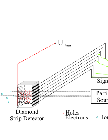
Diamond is an ideal material for beam monitoring. The idea is simple: A strip detector, as has been used in high energy physics for a long time, is put directly in the primary particle beam. (See Fig. 1.) But instead of single particle tracks, a whole bunch (or a continuous beam) of particles creates a profile of signals across many strips. Depending on the beam, either the charges created by a bunch are collected or in case of a continuous beam the current is measured. Plotting the signal height versus the strip positions results in a profile which can be used to determine the beam position and width. Using a fast readout opens the additional possibility of measuring also the time structure of a beam or a bunch of particles resulting in two dimensional beam intensity information, (as will be discussed later). Such diamond beam monitors can in principle replace the usual wire scanners, which measure the transverse profile by moving a thin wire through the beam and measure the scattered particles outside the beampipe as function of the wire position. Moving a diamond strip sensor instead of a wire into the beam has the advantage that one gets a 2D picture of a single bunch instead of a 1D picture averaged over many bunches. This advantage may be particularly important for electron-positron colliders, where every bunch is generated, collided and dumped in the beam dump, so it is important to check the stability of the bunches. For such beam monitors typical resolutions in the range are required, which can be achieved by small pitch strip detectors. The very high mobility of charges inside diamond allow for timing resolutions of the order of 10 ps, so the longitudinal size of the bunch length should be obtainable with a precision of the order of a few mm. In addition, putting orthogonal strips on both sides of the diamond would lead to 3D profile measurements.
In this study no electron beams of this quality were available. Instead the heavy ion plasma beam at GSI was used, which provides transverse sizes of a few mm and bunch lengths of about hundred ns. However, it allows to study the principle of a diamond beam monitor with extreme intensities, so the much more important questions of radiation damage, stability of metallization, saturation etc. can be studied.
Using diamond as detector material has several advantages: a) diamond is much more radiation hard than silicon [1]. b) diamond has a higher band gap, so it does not need a depleted diode structure to reduce the leakage current at room temperature. Consequently it does not have the silicon detector problem of needing depletion voltages above the breakdown voltage after a high irradiation dose, which increases the leakage current; c) diamond has a thermal conductivity five times higher than the thermal conductivity of copper, which allows for high intensity beams through the sensor. The area needed for a beam monitor detector is small, usually 1 cm2 is enough. Therefore the price for a detector grade polycrystalline diamond is negligible compared with the cost for mechanics and electronics. In this study we use polycrystalline detector grade CVD diamond films from Element Six [2] as sensors with aluminium readout strips sputtered on it using a photolithographic mask. The diamond sensor had a thickness of 80 m and a size of 11 cm2. The metallization was done with aluminum for several reasons. One is, that the energy loss of the ions in the metallization should be small to keep the damage low. The others are, that aluminum is easy to bond, easy to process for the manufacturer of the strips and sticks well to the diamond sensor. More details can be found in Ref. [3].
2. Measurements with a heavy ion beam
The measurements presented here, were performed at the GSI444GSI: Gesellschaft für Schwerionenforschung, Darmstadt, Germany. The accelerator facility used for the measurements consists of two parts. The so called UNILAC, a linear preaccelerator and the main accelerator SIS18, a synchrotron ring. There are a few extraction lines from that ring. Our measurements were performed in a vacuum chamber that could also be filled with argon. There were two CCD cameras with photocathodes available to acquire images of the beam passing through the chamber. They detect the light from the recombination of the excited argon atoms. The accelerator can be used to accelerate almost any kind of ion from protons to Uranium up to energies of 4715 MeV/u (protons) or 1025 MeV/u (uranium) [4, 5]. In the measurements presented here, a lead ion () beam was used to generate the signal in the diamond. The ions had a total kinetic energy of 83.2 GeV corresponding to 400 MeV/u. They were extracted in bunches of up to 2.5 ions with a bunch length of 1 s. The bunch structure could be chosen with either one or four intensity maxima. In the latter case the sigma of the bunch is about 100 ns.
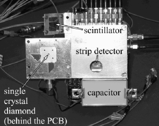
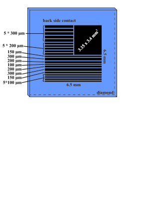
Inside the chamber a computer controlled x-y-z-stage was installed and the diamonds were mounted on that stage. There were two diamonds, one single pad single crystal diamond and one polycrystalline strip detector. (See Fig. 2(a).) Only the results of the polycrystalline strip detector will be presented here. The layout of the metallization on the strip detector is shown in Fig. 2(b).
Twelve of the strips (and the larger pad together with the shorter strips) were connected to a 12 channel GHz-digitizer via the printed circuit board and coaxial cables. Since there are twelve strips and one pad, one cable had to be switched to read out the pad. The backplane on the detector, one continuous metallized square, was connected to the high voltage.
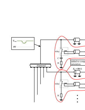
The readout schematics are shown in Fig. 3(a). In addition to the simple coaxial cables there are small resistors of 1 and a capacitor on the high voltage side to reduce the effect of saturation from beam currents up to the Ampere range, which implies ionization currents in the kA range for short bunches. These resistors could be connected and disconnected by relays. The importance for the measurements will be discussed later.
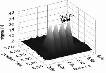
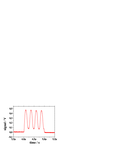
An example of a measured beam profile from the lead-ion beam is shown in Fig. 4(a). In the left panel the 2D structure of the beam is shown: the strip information on the left axis gives the transverse profile, while the timing information (right axis) yields the longitudinal profile. The latter is in perfect agreement with the timing structure from a beam pick up coil, plotted in Fig. 4(b), thus proving that one can get indeed both the longitudinal and transverse profile of a single bunch with a diamond beam monitor.
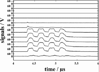
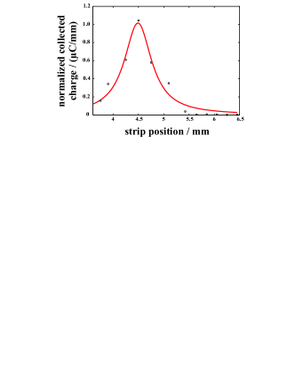
A quantitative determination of the beam width and beam position requires knowledge of the collected charge of each strip after correcting for the strip width and possible non-linear effects from saturation. A raw profile of the 12 digitizer signals is shown in the left panel of Fig. 5. Simply normalizing the signals to the strip width yields the beam profile plotted on the right hand side. The beam position and width can be determined by simply fitting a Lorentzian or Gaussian curve.
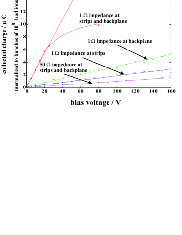
In order to check for non-linear effects measurements were made with several beam intensities. Ionization currents to the digitizer could be reduced by closing the switches in Fig. 3(a). High ionization currents to the digitizer will give an appreciable voltage drop on the 50 input impedance of the digitizer, thus reducing the effective voltage on the sensor and the corresponding charge collection efficiency. Switching on the resistors divides the short ac-pulse of the ionization current between these resistors and the 50 input of the digitizer, thus reducing the voltage drop on the 50 readout impedance, and consequently on the detector, by a factor 100, if both 1 resistors are switched on. In addition, the capacitor helps in stabilizing the high voltage on the detector when the switches are closed. Fig. 3(b) shows the effect of the reduced readout impedance. The total amount of collected charge increases considerably. The observed saturation in that case may be due to the fact that all generated charges were collected for an applied bias voltage of 1 V/m.
The disadvantage of the system with the relays are the relatively long wires needed to connect the relays. Simulations with SPICE555SPICE: Simulation Program with Intgrated Circuit Emphasis showed that these wires with the relatively large inductance and corresponding large voltage drop for high current variations in time, as expected for short bunches, were the reason that the signals were skewed when the resistors were connected to the strips via the relays. This problem might be solved in future by connecting the resistors via short printed circuit connections directly to the strips. Another problem was the crosstalk between the strips when the resistors were connected. The reason could be found in a single cable that connected all resistors with ground on the backside.
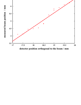
Another measurement concerns the determination of the beam position. This can be done by keeping the beam at a fixed position and moving the detector orthogonally across the beam with the x,y-stage. The profile was then determined at known detector positions and a Lorentz function was fitted to determine the beam position. The determined beam position is plotted versus the detector position in Fig. 6(a), which shows that there are some positions at which the measured beam position deviates several hundred micrometers from the expected positions extracted from the x-y-stage controller. This result is not so bad taking into account the problems calculating the profiles without worrying about non-linearities and the large pitch of the strips, which varies from 100 to 300 m (see Fig. 2(a)).
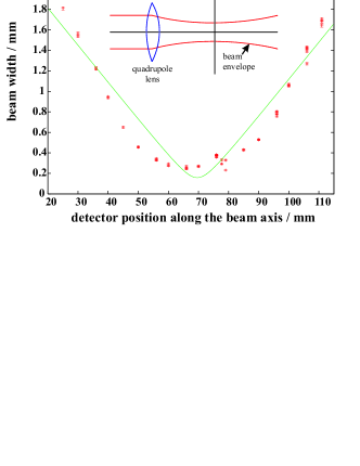
Finally some measurements were done to determine the beam width. First of all the measured profile was compared with a profile determined with a quartz scintillator. The agreement was good, although not perfect. But it is well known that the scintillator saturates at the highest intensities in the center of the beam. Another problem with the scintillator is the fast degradation in the beam. The second test was a scan of the beam longitudinally along the beam axis. The results are plotted in Fig. 6(b) together with a sketch of the geometry of the beam. The idea of the measurement was to use the fact that the lead ion beam is focused inside the vacuum chamber by a quadrupole lens directly in front of it. Therefore there is a relatively steep angle of the beam inside the vacuum chamber. By moving the detector from one end of the box to the other one gets a broad variety of different beam widths, as shown in Fig. 6(b). The observed beam width tracks the expected beam width quite well. The largest deviations were observed for very broad bunches and for very narrow bunches close to the focus point. The first deviations can be explained by the limited width of the area covered by the strips, while for narrow bunches (in the order of the pitch of the strips) the non-linear effects and the skewed signals discussed above leads to uncertainties.
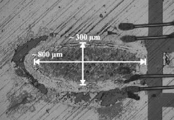
As a final measurement the intensity was increased to the maximum available in order to test if the diamond could be damaged. The detector was biased and several bunches of up to 2.5 lead ions per bunch were fired onto the diamond in a short period of time. A drop in the signal height was not observed, even after several bunches. The only damage that could be observed was in the metallization. A microscopic picture of this damage can be seen in Fig. 7. Although the metal seems to be evaporated at the edges and in the middle of the beam, the damage appeared to have no influence on the signal height. But the dimensions of the damage open the possibility of comparing the measured beam width with the size of the beam. Obviously the results of measuring the beam width in the focal point seem to describe the real beam width very well.
3. Conclusions and Prospects
The presented measurements with a diamond beam monitor show that such a system is competitive with wire scanners as they are for example foreseen for TESLA ([6, 7]). More details on beam monitoring with diamonds compared to wire scanners can be found in [3, 8]. The results prove that such a system gives precise values for the beam position and width without further measurements of pick up probes or the like. All crosschecks showed that a high precision can be achieved.
Some improvements can be made. The main problem is still the large charge generated in every strip. It is essential to keep the bias voltage applied during the interaction of the beam to collect all charge, which can be done by a local capacitor. In addition, a low impedance in the readout chain reduces the voltage drop on the detector. Additional components close to the detector should be connected with thick, very short connections in order to have low inductance. This can be realized with a printed circuit board. A second point is that it would be an advantage to have a smaller pitch of the strips. Strips on the backside could give additional information of the beam width and position in an additional dimension. Smaller strips would also affect the absolute values of the created charge per channel and therefore reduce problems of voltage drop, thus increasing the dynamic range. Additionally using a single crystal diamond instead of a polycrystalline could be interesting for a very narrow beam, as expected in linear colliders. In very narrow beams the beam dimension could be in the range of the single crystal grains in the polycrystalline diamond and the variations in the charge collection efficiency between the grain boundaries could influence the measured profile. Additional improvements of the system could be the use of still thinner diamonds, which would suppress the saturation effects.
The authors would like to thank all members - and specially Serban Udrea and Dmitry Varentsov - of the plasma physics group of Prof. D.H.H. Hoffman at GSI, who offered their beam extraction line and experimental setup for our experiments. In addition we thank the operators of the SIS and Unilac who provided us excellent experimental conditions.
References
- [1] RD42 Collaboration, W. Adam et al., Radiation hard diamond sensors for future tracking applications, Nucl. Instrum. Meth. A 565 (2006) 278
- [2] Element Six, http://www.e6.com/
- [3] J.Bol, Diamond Beam Monitors for Intense Primary Particle Beams, PhD-Thesis IEKP-KA/2006-8, Universität Karlsruhe, 2006, http://www-ekp.physik.uni-karlsruhe.de/pub/web/thesis/iekp-ka2006-8.pdf.
- [4] Gesellschaft für Schwerionenforschung, Betriebsanweisung für die Beschleuniger, (http://www.gsi.de), 2002
- [5] K. Blasche, B. Franczak, B. Langenbeck, G. Moritz, C. Riedel, The Heavy Ion Synchrotron SIS - A Progress Report, Proceedings of the Particle Accelerator Conference (1993).
- [6] The TESLA Collaboration, TESLA - The Superconducting Electron-Positron Linear Collider with an Integrated X-Ray Laser Laboratory, Technical Design Report, (DESY 2001-011) Deutsches Elektronen-Synchrotron DESY, 2001.
- [7] G. Schmidt, U. Hahn, M. Meschkat, F. Ridout, ”First Results of the High Resolution Wire Scanners for Beam Profile and Absolute Beam Position Measurement at the TTF”, FEL’2000 Conference, Nucl. Instr. Methods, vol. A475, pp. 545-548, 2001.
-
[8]
J.Bol, E.Berdermann, W. de Boer, E. Grigoriev, F.Hauler,
L.Jungermann, Beam Monitors for TESLA Based on Diamond Strip
Detectors,
IEEE TRANSACTIONS ON NUCLEAR SCIENCE, VOL. 51, NO. 6, DECEMBER 2004