A widely tunable parametric amplifier based on a SQUID array resonator
Abstract
We create a Josephson parametric amplifier from a transmission line
resonator whose inner conductor is made from a series SQUID array.
By changing the magnetic flux through the SQUID loops, we are able
to adjust the circuit’s resonance frequency and, consenquently, the
center of the amplified band, between 4 and 7.8 GHz. We observe that
the amplifier has gains as large as 28 dB and infer that it adds
less than twice the input vacuum noise.
Josephson parametric amplifiers (JPAs) operate as ultralow noise microwave amplifiers. By detecting only one quadrature of a signal, degenerate parametric amplifiers can add even less noise than the minimum required by quantum mechanics when detecting both quadratures.Takahasi (1965) Josephson parametric amplifiers have been operated with near quantum-limited sensitivityYurke et al. (1989) and have been used to squeeze both thermal and vacuum noise.Yurke (1987); Yurke et al. (1988); Movshovich et al. (1990) In spite of these promising results, they have not been widely adopted since they suffer from two main disadvantages. They have both small dynamic range and narrow band gain; they are well suited to amplify signals only in a narrow range in both power and frequency, limiting their application. Furthermore, compelling applications that would benefit from a lower-noise microwave amplifier have only recently been developed. With the advent of quantum information processing using superconducting circuits,Wallraff et al. (2004); Schuster et al. (2007) there is now a need for practical amplifiers that operate at the limits imposed by quantum mechanics.
The crucial element in a resonant-mode parametric amplifier is a circuit whose resonance frequency can be varied with time. If a reactive parameter oscillates at twice the resonance frequency, energy can be pumped into (or out of) the mode, realizing an amplifier. In practice, this time dependence is often generated through a nonlinear inductance or capacitance. If the nonlinear reactance is proportional to the intensity rather than the amplitude of the mode, then an intense pump tone applied at the resonance frequency automatically creates the necessary parametric oscillation. In analogy with optics, we describe this effect as a Kerr nonlinearity. The nonlinear current-dependent inductance of a Josephson junction,
| (1) |
provides such a Kerr nonlinearity, where is the critical current of the junction, and is the current flowing through it.
Because they are built from nonlinear resonant circuits, Josephson parametric amplifiers are inherently narrowband with limited dynamic range. Only signals close to the circuit’s resonance frequency whose power is small compared to the pump can be linearly amplified. In this paper, we report a novel approach that addresses the limited bandwidth of Josephson parametric amplifiers. We create a JPA from a circuit whose resonance frequency can be adjusted between 4 and 7.8 GHz by applying a magnetic field. The amplifier is still narrowband, but the band center can be adjusted over an octave in frequency. With the amplifier, we demonstrate power gains as large as dB. Furthermore, we can extract the amplifier parameters by measuring the reflectance from the resonator and use them to accurately predict the amplifier’s frequency-dependent gain. Finally, the sensitivity is improved by 16 dB when we place our parametric amplifier in front of a state-of-the-art microwave amplifier (HEMT). This improvement demonstrates that the parametric amplifier provides useful gain and operates much closer to the quantum limit than the HEMT amplifier.
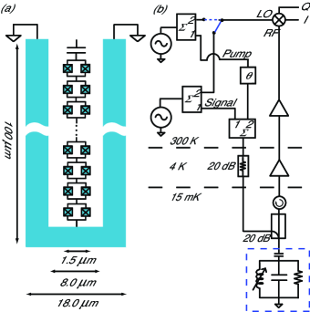
The device we study consists of a quarter-wave coplanar-waveguide (CPW) resonator whose center conductor is an array of SQUIDs in series [Fig. 1(a)]. Two Josephson junctions in parallel form a SQUID, which behaves as a single junction with an effective , where is the magnetic flux enclosed by the SQUID loop in units of flux quanta. By adjusting through the SQUIDs, we can adjust the inductance per unit length of the coplanar waveguide (Eq. 1). Haviland and Delsing (1996) We estimate for one SQUID to be A. The resulting metamaterial has a zero-flux inductance per unit length of mH/m . The CPW has a capacitance per unit length of nF/m, yielding a phase velocity of . We form a resonator by shorting one end of the SQUID array CPW and capacitively coupling the other end to a transmission line. The SQUID array behaves as a lumped element resonatorFeldman et al. (1975); Wahlsten et al. (1977) close to its resonance frequency; it is not a distributed parametric amplifier.Sweeny and Mahler (1985); Yurke et al. (1996)
The parametric amplifier is operated in reflection mode, as shown in Fig. 1(b). Two signal generators create two tones, a pump at frequency and a signal at . The two tones are summed before being injected into a dilution refrigerator operating at mK. They are attenuated by dB at K. A directional coupler at mK provides an additional dB of attenuation and separates the incident tones from the reflected tones. Thus, including the 8-12 dB of loss from cables, incident tones and room-temperature Johnson noise are attenuated by about dB.
Because of the nonlinearity of the metamaterial, the pump and signal tones mix. This mixing amplifies the signal and creates an idler, or intermodulation tone, at a frequency . To further amplify the signals coming out of our resonator, we use a cryogenic HEMT amplifier with noise temperature K and another set of low noise amplifiers at room temperature. An isolator at base temperature prevents the noise emitted by the input of the HEMT amplifier from exciting the JPA. Amplitudes and phases of the signals at the output of the room temperature amplifiers are recovered with an IQ demodulator whose local oscillator (LO) can be provided by either microwave generator.
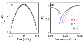
Before operating the parametric amplifier, we characterize the resonator’s reflectance with just a pump tone. We first study the flux dependence of the resonator by measuring the real (I) and imaginary (Q) part of the reflection coefficient as a function of frequency. The resonance frequency is identified by a dip in . Figure 2(a) shows how the resonance frequency behaves as a function of . The applied flux increases , reducing and consequently .
By measuring as a function of frequency and incident power, we obtain the linear and nonlinear resonator parameters [Fig. 2(b)]. At low enough incident power , where the resonator response is linear, we extract the damping rates associated with the coupling capacitor and the linear dissipation in the resonator . We extract these from the halfwidth [] and the depth of the dip [] in at the resonance frequency . For a flux of , we find the resonator’s linear parameters GHz, MHz, and MHz. As we increase the pump power, the Kerr nonlinearity makes the resonance frequency decrease according to the equation , where is the frequency at which is minimum, is the Kerr constant, and is the energy stored in the resonator.Yurke and Buks (2006) Above the critical power , is discontinuous, and the resonators response is bistable. From the frequency and power dependence of , we estimate the critical power and Kerr constant to be fW and , respectively. The large uncertainty comes from the dB uncertainty of the incident power on the resonator. From Appendix A in Ref. Yurke and Buks, 2006, we can calculate the Kerr constant from the number of SQUIDs and their . The expected value for the Kerr constant is , in agreement with our measurement. To model more completely the behavior of the resonator, we also include a nonlinear dissipation term , which is the imaginary part of the Kerr constant. From the physical characteristics of the resonator, we can predict , , and ; however we do not yet understand the physical origin of and .
The analysis of the parametric amplifier follows closely the theory developed by Yurke and Buks for parametric amplification in superconducting resonators.Yurke and Buks (2006) In their model, the Kerr nonlinearity is provided by the intrinsic kinetic inductance of a superconducting film,Tholen et al. (2007) while in our case it arises from the nonlinear Josephson inductance of the SQUIDs (Eq. 1).
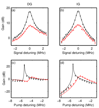
The intermodulation gain (IG) and direct gain (DG) can be predicted from the resonator’s parameters. We define DG as the ratio between the reflected signal power with the pump on and the incident signal power; IG is the ratio between the intermodulation tone and the incident signal. To verify the behavior of the parametric amplifier, we operate it in the nondegenerate mode and measure the frequency dependence of both gains in two different ways. In the nondegenerate mode, the signal and the pump frequencies are different, and the generator that creates the signal tone also provides the LO to the demodulator. In the first test, we apply the pump at a frequency close to and analyze DG and IG as we detune the signal frequency from the pump by an amount . In Figs. 3(a) and 3(b), we plot both IG and DG as a function for two different pump powers. We also plot the predictions from the theory in Ref. Yurke and Buks (2006) where the parameters in the theory are extracted from the measurements of . From this plot, we estimate the dB bandwidth to be about kHz when DG and IG are dB. Next, we measure IG and DG as a function of pump detuning, i.e., the difference in frequency between the applied pump and . In this test, the signal and the pump frequency differ by a fixed amount, kHz, [Figs. 3(c) and 3(d)]. From the agreement seen in Fig. 3, we conclude that Ref. Yurke and Buks, 2006 provides an appropriate model for our device.
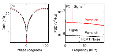
For GHz (), we have also operated the JPA in a doubly degenerate mode where the pump and the signal frequencies are the same. In this mode, the gain of the parametric amplifier is sensitive to the phase between the pump and the signal. To measure this phase dependence, we amplitude modulate the signal at kHz and adjust the phase of the pump relative to the signal. We define the gain as the ratio of the AM modulation sideband power with the pump on and pump off. Because the local oscillator frequency and the pump frequency are the same, the signal and intermodulation tones are added at the output of the demodulator, giving a total gain 3 dB larger than either DG or IG. In degenerate mode, the gain can be 3 dB larger than in nondegenerate mode if the phase between the pump and signal is tuned for maximum gain. The phase dependence of the gain for a pump power close to is shown in Fig. 4(a); there it is evident that we see deamplification, a hallmark of degenerate parametric amplifiers. In Fig. 4(b), we plot the power spectral density (PSD) of the demodulated signal with the pump off and pump on for , where the signal-pump phase has been adjusted for maximum gain ( dB). At this gain, the HEMT amplifier’s input noise is overwhelmed by the noise at the output of the parametric amplifier, effectively improving the signal-to-noise ratio (S/N) by dB. A definitive measurement of the noise added by our parametric amplifier will require a calibrated noise source. We have not yet completed this measurement. However, by measuring the S/N with the pump off, we find that the noise referred to the input of the HEMT is K. From the S/N improvement with the pump on, we estimate the total noise referred to the input of the JPA as mK. This value suggests that the parametric amplifier adds an amount of noise comparable to the vacuum noise ( mK), which must be present at the input of the JPA.
To demonstrate the tunability of the JPA, we also test the performance of the amplifier at lower frequencies. For example, for , the resonance frequency is GHz. A similar analysis as the one described for gives the following parameters: MHz, MHz, fW, and . The increase in the nonlinear loss degrades the performance of the amplifier, making the measured gains smaller than the ones at GHz. The highest IG and DG observed at this frequency are both dB.
Although the power-handling capacity of this device is low (critical powers of the order of a few femtowatts), its performance is appropriate for amplifying the signals generated by superconducting qubits. By virtue of the tunability of our amplifier’s band, it can be brought into resonance with a second high-Q superconducting resonator used to study superconducting qubits as in Refs. Wallraff et al., 2004 and Schuster et al., 2007. For more general applications where larger signals need to be amplified, similar parametric amplifiers could be used if the critical current of the SQUIDs is made larger.
In conclusion, we have demonstrated a widely tunable parametric amplifier based on a coplanar waveguide resonator whose inner conductor is made from a SQUID array. We have observed tunability over an octave and gains as high as dB. Although the resonator is composed of discrete elements, its behaviour is well described by a continuum theory of parametric amplification.Yurke and Buks (2006) Finally we have demonstrated that the JPA is 16 dB more sensitive to a weak microwave signal than a low-noise HEMT amplifier, suggesting that the JPA adds less than twice the vacuum noise.
The authors thank S. M. Girvin for valuable conversations. K. W. Lehnert is a member of NIST’s Quantum Physics Division.
References
- Takahasi (1965) H. Takahasi, Adv. Comm. Syst. 1, 227 (1965).
- Yurke et al. (1989) B. Yurke, L. R. Corruccini, P. G. Kaminsky, L. W. Rupp, A. D. Smith, A. H. Silver, R. W. Simon, and E. A. Whittaker, Phys. Rev. A 39, 2519 (1989).
- Yurke (1987) B. Yurke, J. Opt. Soc. Am. B 4, 1551 (1987).
- Yurke et al. (1988) B. Yurke, P. G. Kaminsky, R. E. Miller, E. A. Whittaker, A. D. Smith, A. H. Silver, and R. W. Simon, Phys. Rev. Lett. 60, 764 (1988).
- Movshovich et al. (1990) R. Movshovich, B. Yurke, P. G. Kaminsky, A. D. Smith, A. H. Silver, R. W. Simon, and M. V. Schneider, Phys. Rev. Lett. 65, 1419 (1990).
- Wallraff et al. (2004) A. Wallraff, D. I. Schuster, A. B. L. Frunzio, R.-S. Huang, J. Majer, S. Kumar, S. M. Girvin, and R. J. Schoelkopf, Nature 431, 162 (2004).
- Schuster et al. (2007) D. I. Schuster, A. A. Houck, J. A. Schreier, A. Wallraff, J. M. Gambetta, A. Blais, L. Frunzio, J. Majer, B. Johnson, M. H. Devoret, S. M. Girvin, and R. J. Schoelkopf, Nature 445, 515 (2007).
- Haviland and Delsing (1996) D. B. Haviland and P. Delsing, Phys. Rev. B 54, 6857 (1996).
- Wahlsten et al. (1977) S. Wahlsten, S. Rudner, and T. Claeson, J. Appl. Phys. 49, 4248 (1977).
- Feldman et al. (1975) M. J. Feldman, P. T. Parrish, and R. Y. Chiao, J. Appl. Phys. 46, 4031 (1975).
- Sweeny and Mahler (1985) M. Sweeny and R. Mahler, IEEE Trans. Magn. 21, 654 (1985).
- Yurke et al. (1996) B. Yurke, M. L. Roukes, R. Movshovich, and A. N. Pargellis, Appl. Phys. Lett. 69, 3078 (1996).
- Yurke and Buks (2006) B. Yurke and E. Buks, J. Lightwave Technol. 24, 5054 (2006).
- Tholen et al. (2007) E. A. Tholen, A. Ergul, E. M. Doherty, F. M. Weber, F. Gregis, and D. B. Haviland, cond-mat/0702280 (2007).