Meta-nematic transitions in a bilayer system: Application to the bilayer ruthenate
Abstract
It was suggested that the two consecutive metamagnetic transitions and the large residual resistivity discovered in Sr3Ru2O7 can be understood via the nematic order and its domains in a single layer system. However, a recently reported anisotropy between two longitudinal resistivities induced by tilting the magnetic field away from the axis cannot be explained within the single layer nematic picture. To fill the gap in our understanding within the nematic order scenario, we investigate the effects of bilayer coupling and in-plane magnetic field on the electronic nematic phases in a bilayer system. We propose that the in-plane magnetic field in the bilayer system modifies the energetics of the domain formation, since it breaks the degeneracy of two different nematic orientations. Thus the system reveals a pure nematic phase with a resistivity anisotropy in the presence of an in-plane magnetic field. In addition to the nematic phase, the bilayer coupling opens a different route to a hidden nematic phase that preserves the - symmetry of the Fermi surfaces.
pacs:
71.10.Hf,71.20.-b,71.55.-i,73.22.Gk,73.43.NqI Introduction
Electronic liquid crystal phases have been widely discussed in the context of doped Mott insulators, Kivelson et al. (1998, 2003) and have attracted much attention with the discovery of anisotropic quantum Hall phases in GaAs heterostructures in large magnetic fields.Lilly et al. (1999); Du et al. (1999); Cooper et al. (2004) In particular, the anisotropy in the longitudinal magnetoresistivities in the bilayer ruthenate Sr3Ru2O7 strongly suggests the existence of an anisotropic metallic phase dubbed an electronic nematic phase.Borzi et al. (2007)
In experiments on ultrapure Sr3Ru2O7 in magnetic fields along the axis, an unusual phase characterized by a pronounced residual resistivity emerges in the vicinity of a putative quantum critical point. Furthermore, this phase is bounded by two consecutive meta-magnetic transitions. Grigera et al. (2001); Perry et al. (2001); Gegenwart et al. (2006); Perry et al. (2005); Grigera et al. (2004) Upon tilting the field slightly towards one of the in-plane crystal axes, a magnetoresistive anisotropy appears, where the pronounced resistive anomaly parallel to the in-plane field direction remains unchanged, but disappears in the perpendicular direction.
It was proposed that the two consecutive meta-magnetic transitions occur due to the formation of nematic order.Kee and Kim (2005) As a consequence of the nematic order, one expects to find an anisotropy in the longitudinal resistivities in the pure nematic phase due to the Fermi surface distortion, but this has not been observed in Sr3Ru2O7 in magnetic fields along the axis. Instead, the pronounced resistivity shows up in the proposed nematic region bounded by two metamagnetic transitions. The large resistivity was explained by scattering due to domains of two degenerate nematic orientations. Doh et al. (2006b) However, when the magnetic field is tilted away from the axis, the transport anisotropy is discovered. This cannot be understood within the previous nematic order proposal, since the Zeeman coupling and the energetics of the domains are independent of the magnetic field direction in the single layer system.
In this paper, we attempt to understand the recently reported magnetoresistive anisotropy in the presence of an in-plane magnetic field. We show that the magnetoresistive anisotropy in the presence of an in-plane magnetic field can be understood within the nematic order picture when one takes into account the bilayer coupling. Note that the in-plane magnetic field in the bilayer lattice causes a relative momentum mismatch between the layers. When the in-plane field is along one of the crystal axes, it breaks the degeneracy of two different nematic orientations. Consequently, domains with different nematic orientations are no longer energetically favorable, and the system exhibits a pure nematic phase with a Fermi surface elongation. Thus, the anisotropy in transport is recovered in the presence of an in-plane magnetic field.
The paper is organized as follows. We introduce the bilayer model in Sec. II. In Sec. III, we identify the distinctly different nematic phases and present the phase diagram as a function of the bilayer coupling and chemical potential. We also discuss a hidden nematic phase which is absent in the single layer system. An in-plane magnetic field is incorporated in Sec. IV, where we study the phase diagram under the in-plane magnetic field and the signatures of meta-nematic transitions in the longitudinal conductivity and the magnetic susceptibility. We close with a discussion and a summary of our findings in Sec. V.
II Bilayer model
In the electronic nematic phase, electron momenta prefer to be aligned along a certain direction, typically along one of the crystal axes, thus breaking a point-group symmetry of the underlying lattice. A number of models have been employed to study the formation of electronic nematic order. The approach adopted in the present work is based on the idea of a broken symmetry state of an isotropic liquid. Yamase et al. (2000a); Halboth and Metzner (2000); Oganesyan et al. (2001); Kee et al. (2003); Khavkine et al. (2004); Nilsson and Neto (2005); Quintanilla and Schofield (2006); Yamase et al. (2005a); Lawler et al. (2006a, a); Metzner et al. (2006a); Dell’Anna and Metzner (2006b); Edegger, Muthukumar and Gros (2006b); Wu, Sun, Fradkin, and Zhang (2007b) Here, the formation of the nematic phase is due to a spontaneous Fermi surface distortion often referred to as a Pomeranchuk instability. Pomeranchuk (1958) It was found, however, that the divergence of the nematic susceptibility, which defines the Pomeranchuk instability, is preempted by a first order transition, and that the formation of an electronic nematic phase on a lattice is intimately connected to the van Hove singularities in the density of states (DOS).Kee et al. (2003); Khavkine et al. (2004)
The effective nematic interaction successfully describes several novel phenomena observed in Sr3Ru2O7.Kee and Kim (2005); Doh et al. (2006b) We generalize the quadrupole density interaction for a bilayer square lattice as follows,
| (1) | |||||
where the symmetric and traceless tensors are given by
| (2) | |||
| (5) |
Here, denotes the layer index, the spin degree of freedom, and , the electronic creation and annihilation operators. The functions and denote intraplane and interplane quadrupolar density interactions, respectively. The order parameter is defined through the tensors in analogy to its counterpart in classical liquid crystal theory. In conjunction with the tight-binding model on a square lattice, the intralayer interaction term in Eq. (1) describes the first order transition between isotropic and nematic states within a mean-field theory. Kee et al. (2003); Khavkine et al. (2004)
In general, there are two distinct nematic orders in a single layer square lattice system. The preferred direction of the electron momenta can be aligned either parallel or diagonal to the crystal axes. Previous studies of monolayer systems have shown, however, that diagonal order is generally suppressed for the model given by Eq. (1). Doh et al. (2006a); Kao and Kee (2005); Kao et al. (2007b) We, therefore, concentrate on the nematic phase parallel to the in-plane crystal axes. Assuming an attractive interlayer interaction potential () and a generally attractive intralayer interaction , the components of the parallel order parameter are defined by
| (6) |
where a positive (negative) value signals, that electron momenta are preferentially aligned along the () axis. Note that the order parameter is defined layerwise (). Within the mean-field (MF) approximation, the Hamiltonian then becomes
| (7) | |||||
where is the interlayer hopping amplitude.
To consider the effect of an in-plane magnetic field, we incorporate the field via Peierls substitution and Zeeman coupling. Assuming that , the magnetic flux in the x-direction through a single plaquette is given by , as the layer separation in Sr3Ru2O7 is of about the same order as the planar lattice parameter . Normalized by the flux quantum , the flux causes the following relative momentum mismatch between the layers:
| (8) |
The electronic dispersions for each layer in the presence of an in-plane magnetic field are given by
| (9) | |||||
where for the lower layer (). In Eq. (9), we introduced the chemical potential and an effective magnetic moment (), while stands for spin-up and spin-down. Taking into account the bilayer coupling , the hybridized energy bands read
| (10) |
where the order parameter components satisfy the set of mean-field equations ()
| (11) |
The expectation values depend in a non-linear fashion on all . Both dispersions of Eq. (10) are mapped onto each other under a particle-hole transformation.
In the following, we calculate the free energy using an adaptive integration scheme and solve the set of mean-field equations self-consistently. We first present the effects of the bilayer couplings and on nematic order in the absence of a magnetic field (). Based on the zero-field results, we then deduce the effect of an in-plane magnetic field originating from the bilayer coupling . Finally, we include the Zeeman term and investigate the signatures of nematic order in magnetization and transport.
III Nematic phases in a bilayer system
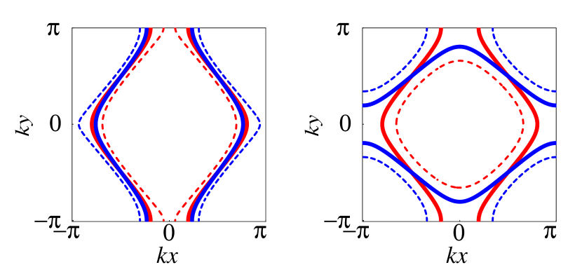
Let us first identify possible nematic phases in the absence of external fields (). The spin index is redundant and the state of the system is specified by a layer-dependent order parameter (). As none of the crystal directions is distinguished, both components of the order parameter have the same magnitude, . This implies that, besides the isotropic phase, where , only twofootnote (2007b) distinct nematic phases can occur as shown in Fig. 1: a parallel nematic phase, where and a ”hidden” nematic phase, where . In the hidden nematic phase, the prehybridized Fermi surface of one layer is elongated along the () direction, while the prehybridized Fermi surface of the other layer is stretched along the () axis. However, taking into account the bilayer coupling, each of the hybridized energy bands shown as the thick lines in Fig. 1 preserves the - symmetry, but breaks the relative symmetry between the layers, . A similar phase called the phase, where up-spin and down-spin Fermi surfaces are elongated perpendicular to each other, was reported.Wu, Sun, Fradkin, and Zhang (2007b)
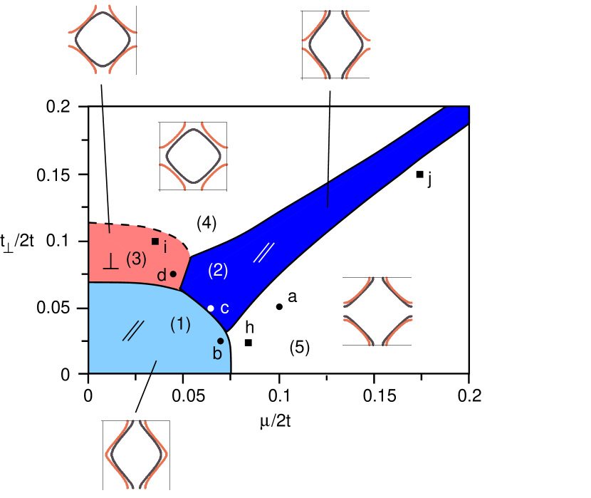
We study the phase diagram as a function of bilayer coupling and chemical potential . The phase diagram shown in Fig. 2 is obtained for and . It shows that the parallel nematic phase, labeled by (1) and (2) in Fig. 2, is favored along the diagonal region () of the phase diagram. The hidden nematic phase (3) on the other hand, emerges as an intermediate phase at intermediate values for and is separated by a second order phase boundary from the neighboring isotropic regime (4). All the other phase boundaries in Fig. 2 are of first order, and involve a sudden change in the magnitude and/or orientation of the Fermi surface distortion dubbed nematicity. Note that, while the nematicity suddenly changes, there is no further symmetry breaking associated with the transition from one nematic phase to another. We call such a transition a “meta-nematic” transition in analogy to a meta-magnetic transition, where the magnetization jumps without any further symmetry breaking. The insets in Fig. 2 display the different Fermi surface topologies associated with the nematic phases in the bilayer system.
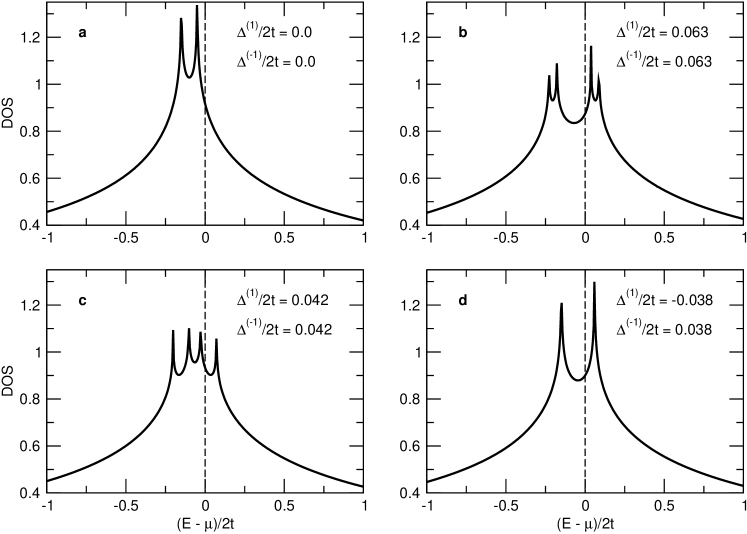
To gain a better understanding of the different types of nematic order in the phase diagram, we study the behavior of the DOS, since it was shown that nematic order develops in order to avoid a van Hove singularity.Kee et al. (2003) In Fig. 3, we present the DOS for the points (a)-(d) as marked in Fig. 2. Originating from the underlying tight-binding dispersion, the bilayer DOS exhibits two peaks in the absence of nematic order, which are separated by as shown in Fig. 3 (a).
As we discussed above, nematic order prevents the Fermi level from lying at the van Hove singularity. However, there is more than one channel to avoid a van Hove singularity in the bilayer system. Each of the original peaks can split into two new singularities, which leads to the parallel nematic phase and is similar to the single layer case. In total, this gives rise to four singularities as shown in Fig. 3 (b) and (c), where the separation between two new peaks is given by . In the hidden nematic phase, in contrast, the two original peaks shift further away from each other such that the mutual separation becomes greater than the bare hybridization as shown in Fig. 3 (d). The peak separation then becomes , which is always greater than . This channel, leading to the hidden nematic phase, is absent in a monolayer system.
IV Effect of in-plane magnetic field
As we discussed above, the two consecutive metamagnetic transitions and the large residual resistivity bounded by the metamagnetic transitions can be understood within the nematic order proposal for a single layer square lattice. However, the recently discovered anisotropy between two longitudinal resistivities induced by tilting the magnetic field away from the c-axis cannot be explained within the nematic order scenario in a single layer, since the Zeeman coupling and the energetics of possible domains in a single layer system are independent of the magnetic field direction.
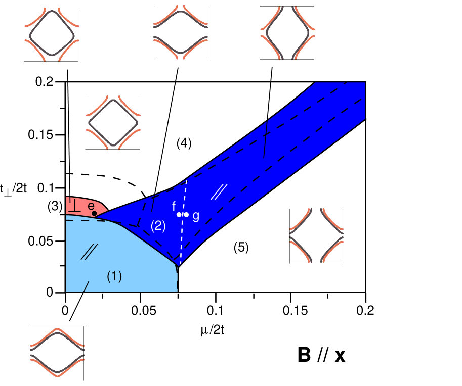
However, note that Ru in Sr3Ru2O7 forms a bilayer layer square lattice, and the in-plane magnetic field has a dramatic effect in the bilayer lattice. For example, a field leads to a mismatch between the upper and lower layer, where the momentum difference , while remains unchanged. The - symmetry breaking field lifts the degeneracy between the two nematic orientations, and thus the phase separation with domains is no longer energetically favorable. Hence the system recovers a pure nematic phase with an anisotropy in the longitudinal transport. Before we present signals of the anisotropy in various quantities, let us first study how the in-plane magnetic field affects the phase diagram of Fig. 2. The phase diagram in the presence of an in-plane magnetic field () is shown in Fig. 4. At this point we do not take into account the Zeeman coupling, but consider it in the subsection below. The phase boundaries in the absence of an in-plane field (dashed lines) are also plotted, to make a comparison with the case without the in-plane magnetic field.
Since the in-plane magnetic field breaks the - symmetry, the hidden nematic phase denoted by (3) in Fig. 4 is suppressed under the in-plane field. Naturally, the second order transition between the isotropic and hidden nematic phase in the absence of an in-plane magnetic field changes to a first order transition due to the presence of a symmetry breaking field. On the other hand, the regions with parallel nematic order are enhanced by the in-plane field, which is also expected. While the suppression/enhancement of the hidden/parallel nematic phases under the in-plane magnetic field are rather robust features, the orientations of the Fermi surface elongations shown in the insets depend on the details of the bare band dispersion and the location of the van Hove singularities. In the Appendix, we present the DOS at the points (e)-(g) in Fig. 4 under the in-plane magnetic field to understand the relation between the nematic orientations and the van Hove singularities.
IV.1 Conductivity and Magnetization
In this section, we present conductivity, magnetization and susceptibility as a function of the magnetic field strength (). We then propose a possible connection between the nematic phase and the phenomena reported in the bilayer ruthenate, Sr3Ru2O7. In addition to the momentum mismatch due to the magnetic field discussed above, the Zeeman coupling is important to take into account, since it acts as a spin dependent chemical potential.
The longitudinal conductivities are computed using the following standard Boltzmann equation
| (12) |
where we set , originating from impurity scattering, to be constant, while is the Fermi-Dirac distribution function and stands for the Fermi velocity. The magnetization and susceptibility are given by
| (13) |
and
| (14) |
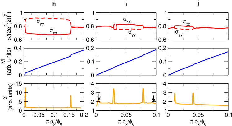
The conductivity, magnetization, and susceptibility as a function of in-plane magnetic field are shown in Fig. 5 for and . The points marked as (h), (i), and (j) in Fig. 2 show the values of the chemical potential and the bilayer coupling used for each panel from left to right, respectively.
Let us first consider the case when the system is in the hidden nematic phase in the absence of a magnetic field [for instance, close to point (i) in Fig. 2]. As the magnetic field increases, the system will undergo several transitions. The isotropic-hidden nematic phase transition at a weak field is hardly visible in the conductivity and magnetization in Fig. 5 (i), although the emergence of the nematic order parameter is accompanied by an anomaly in the susceptibility as indicated by the left arrow in the susceptibility figure. At larger magnetic fields isotropic-parallel nematic transitions occur and are clearly signaled by the onset and offset of the conductivity anisotropy and the jumps in the magnetization.
On the other hand, consider that the system is in the isotropic phase in the absence of a magnetic field, but close to the nematic instability [see e.g. points (h) and (j) in Fig. 2]. As the magnetic field is turned on, parallel nematic order develops in either the up or the down spin species, while the Fermi surface of the other spin species stays isotropic. Then the longitudinal conductivity and the magnetization show clear indications of the isotropic-parallel nematic transition. While the preferred direction of the Fermi surface elongation in the presence of the symmetry breaking field depends on the details of the band structure and the chemical potential, a difference between and is clearly visible in (h) and (j) in Fig. 5. Considering the in-plane field along the direction, we find that the conductivity perpendicular to the field () is higher near half-filling as shown in Fig. 5 (h). Since the Hall conductivity is much smaller than the longitudinal components, the resistivity is almost inversely proportional to the conductivity. Thus the resistivity parallel to the field direction is higher than that perpendicular to the field direction in panel (h), which is consistent with the observed anisotropy in Sr3Ru2O7.Borzi et al. (2007)
V Discussion and Summary
Motivated by the recent experiment on the bilayer ruthenateBorzi et al. (2007), we address the following question: can one explain the magnetoresistive anisotropy within the nematic order scenario which successfully describes both the metamagnetic transitions and the large residual resistivity Kee and Kim (2005); Doh et al. (2006b)? To understand the motivation of our study, one needs to recognize that the formation of nematic order in a single layer is insensitive to the direction of the magnetic field, and thus at first glance, the nematic theory cannot account for all the existing phenomena. However, here we show that the recently discovered magnetoresistive anisotropy can be explained within the picture of nematic order when the bilayer coupling is taken into account. It is essential to note that the in-plane magnetic field leads to a relative momentum mismatch between the layers through bilayer coupling. When the field is along one of the in-plane crystal axes, it breaks the - symmetry. Therefore, the degeneracy of two different nematic orientations is no longer present, and the system recovers a pure nematic phase with anisotropic resistivities.
To study the effects of an in-plane magnetic field on the nematic phases in a bilayer system, we first identify distinct nematic phases in the bilayer system. While the nematic phase always breaks the - symmetry in the single layer system, we find that there is another route to form a different nematic phase called the hidden nematic phase where the - symmetry is preserved. The hidden nematic and the isotropic phase are separated by a second order phase transition. While the - anisotropy is absent in both phases, the relative rotational symmetry between the layers is broken in the hidden nematic phase.
The effect of the in-plane field is rather straightforward when one recognizes the importance of the bilayer structure in Sr3Ru2O7. As discussed above, since the in-plane field is an - symmetry breaking field, there is no spontaneously broken - symmetry in the presence of an in-plane magnetic field. It is clear that the two-fold degeneracy is no longer present, and domains cannot be formed under the same mechanism as described in Ref. Doh et al., 2006b: one of the Fermi surface elongations is energetically preferred over the other for any small amount of in-plane field. Thus the system recovers the intrinsic anisotropy, unless it is in the hidden nematic phase. Based on the analysis of longitudinal conductivities and magnetic susceptibilities, we propose that Sr2RuO7 is close to the parallel nematic instability in the absence of a magnetic field.
One may question the validity of the mean field theory adopted in the current paper, since it is widely accepted that Sr3Ru2O7 is a strongly correlated material with a putative quantum critical point. It is true that a mean field theory breaks down close to a quantum critical point due to large fluctuations, and it is plausible that large fluctuations are important to determine an effective Hamiltonian. However, one should note that we attempt to describe the ordered state and its first order transition to the isotropic phase. Since a mean field theory works quite well deep inside an ordered state due to negligible fluctuations, and the effects of fluctuation on a first order transition are not as important as for a second order transition, we argue that the mean field theory with nematic order qualitatively captures the phenomena discussed above.
There are strong indications that a magnetic field tuned nematic phase bounded by isotropic regions exists in the bilayer ruthenate. In addition to the phenomena discussed above, a recent scanning tunneling microscopy experiment under a axis field revealed the splitting of singularities in the local DOS across the metamagnetic transition.Iwaya et al. (2007) However, further experiments to detect a direct Fermi surface anisotropy, such as scanning tunneling microscopy under in-plane magnetic fields, are highly desirable.Doh et al. (2007b) A microscopic mechanism for the formation of a nematic phase beyond the effective model HamiltonianKee et al. (2008b), and the effects of disorder in relation to a putative quantum critical point are also important subjects for theoretical studies which we will address in the future.
Acknowledgements.
We thank Stephen Julian and Eduardo Fradkin for useful discussions. This work was supported by NSERC of Canada, Canada Research Chair, Canadian Institute for Advanced Research, and Alfred P. Sloan Foundation (HYK).VI appendix
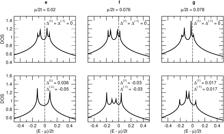
Here we present the DOS (Fig. 6) in the presence of an in-plane magnetic field, to understand the correlation between the preferred direction of Fermi surface elongation and the locations of the van Hove singularities. We set , , , and . The values of chemical potential used for the DOS correspond to those at the points (e)-(g) in Fig. 4. In the absence of an in-plane magnetic field, there are two peaks separated by the bilayer coupling, . However, the in-plane magnetic field splits each of the peaks into two peaks such that there are four singularities in the DOS. The top row shows the DOS of the underlying tight-binding bilayer model in the presence of an in-plane magnetic field, where the magnetic field induces a splitting of the tight-binding singularities into asymmetric peaks. Here, we force the nematicity to be zero in order to see the effect of finite nematicity on the DOS, which is shown in the bottom row of Fig. 6. The three bottom panels represent three different ways of avoiding van Hove singularities in the presence of a finite magnetic field, which can be found by comparing the top and bottom panels for each case. In (e), a finite nematic order with two different orientations for each layer turns four peaks into two peaks such that the Fermi level is further away from the modified singularity. In (f) and (g), parallel nematic order not only splits the two peaks near the Fermi level further apart from each other, but also shifts the weight of the DOS between the singularities. In all three cases, nematic order leads to a further separation between the Fermi level and the nearby van Hove singularity. This analysis helps us understand the orientations of the Fermi surface elongation for the particular set of parameters used here, and one should bear in mind that the preferred direction of the Fermi surface distortion is sensitive to the parameters used in the nematic theory, since van Hove singularities depend on the details of the band structure.
References
- Kivelson et al. (1998) S. A. Kivelson, E. Fradkin, and V. J. Emery, Nature 393, 550 (1998).
- Kivelson et al. (2003) S. A. Kivelson, E. Fradkin, V. Oganesyan, I. P. Bindloss, J. M. Tranquada, A. Kapitulnik, and C. Howald, Rev. Mod. Phys. 75, 1201 (2003) and references therein.
- Lilly et al. (1999) M. P. Lilly, K. B. Cooper, J. P. Eisenstein, L. N. Pfeiffer, and K. W. West, Phys. Rev. Lett. 82, 394 (1999).
- Du et al. (1999) R. R. Du, D. C. Tsui, H. L. Stormer, L. N. Pfeiffer, K. W. Baldwin, and K. W. West, Solid State Comm. 109, 389 (1999).
- Cooper et al. (2004) K. B. Cooper, J. P. Eisenstein, L. N. Pfeiffer, and K. W. West, Phys. Rev. Lett. 92, 026806 (2004).
- Borzi et al. (2007) R. A. Borzi, S. A. Grigera, J. Farrell, R. S. Perry, S. J. S. Lister, S. L. Lee, D. A. Tennant, Y. Maeno, and A. P. Mackenzie, Science 315, 214 (2007).
- Grigera et al. (2001) S. A. Grigera, R. S. Perry, A. J. Schofield, M. Chiao, S. R. Julian, G. G. Lonzarich, S. I. Ikeda, Y. Maeno, A. J. Millis, and A. P. Mackenzie, Science 294, 329 (2001).
- Perry et al. (2001) R. S. Perry, L. M. Galvin, S. A. Grigera, L. Capogna, A. J. Schofield, A. JMackenzie, M.Chiao, S. R. Julian, S. Ikeda, S. Nakatsuji, Y. Maeno, C. Pfleiderer, Phys. Rev. Lett. 86, 2661 (2001).
- Gegenwart et al. (2006) P. Gegenwart, F. Weickert, M. Garst, R. S. Perry, and Y. Maeno, Phys. Rev. Lett. 96, 136402 (2001).
- Perry et al. (2005) R. S. Perry T. Tayama K. Kitagawa T. Sakakibara K. Ishada and Y. Maeno, J. Phys.Soc. Jpn. 74, 1270 (2005).
- Grigera et al. (2004) S. A. Grigera, P. Gegenwart, R. A. Borzi, F. Weickert, A. J. Schofield, R. S. Perry, T. Tayama, T. Sakakibara, Y. Maeno, A. G. Green, Science 306, 1154 (2004).
- Kee and Kim (2005) H.-Y. Kee and Y. B. Kim, Phys. Rev. B 71, 184402 (2005).
- Doh et al. (2006b) H. Doh, Y. B. Kim, and K. H. Ahn Phys. Rev. Lett 98, 126407 (2007b).
- Kee et al. (2003) H.-Y. Kee, E. H. Kim, and C.-H. Chung, Phys. Rev. B 68, 245109 (2003).
- Khavkine et al. (2004) I. Khavkine, C.-H. Chung, V. Oganesyan, and H.-Y. Kee, Phys. Rev. B 70, 155110 (2004).
- Yamase et al. (2000a) H. Yamase, and H. Kohno J. Phys. Soc. Jpn. 69, 332 (2000).
- Halboth and Metzner (2000) C. J. Halboth and W. Metzner, Phys. Rev. Lett. 85, 5162 (2000).
- Oganesyan et al. (2001) V. Oganesyan, S. A. Kivelson, and E. Fradkin, Phys. Rev. B 64, 195109 (2001).
- Nilsson and Neto (2005) J. Nilsson and A. H. C. Neto, Phys. Rev. B 72, 195104 (2005).
- Quintanilla and Schofield (2006) J. Quintanilla and A. J. Schofield, Phys. Rev. B 74, 115126 (2006).
- Yamase et al. (2005a) H. Yamase, V. Oganesyan, and W. Metzner Phys. Rev. B 72, 35114 (2005).
- Lawler et al. (2006a) M. Lawler, and E. Fradkin, Phys. Rev. B 75, 033304 (2006a).
- Lawler et al. (2006a) M. Lawler, V. Fernandez, D. Barci, E. Fradkin, and L. Oxman, Phys. Rev. B 73, 085101 (2006a).
- Metzner et al. (2006a) W. Metzner, D. Rohe, and S. Andergassen, Phys. Rev. Lett. 91, 066402 (2003b).
- Dell’Anna and Metzner (2006b) L. Dell’Anna, and W. Metzner, Phys. Rev. B 73, 045127 (2006b).
- Edegger, Muthukumar and Gros (2006b) B. Edegger, V. N. Muthukumar, and C. Gros, Phys. Rev. B 74, 165109 (2006b).
- Wu, Sun, Fradkin, and Zhang (2007b) C. Wu, K. Sun, E. Fradkin, and S. C. Zhang, Phys. Rev. B 75, 115103 (2007b).
- Pomeranchuk (1958) I. J. Pomeranchuk, Sov. Phys. JETP 8, 361 (1958).
- Doh et al. (2006a) H. Doh, N. Friedman, and H.-Y. Kee, Phys. Rev. B 73, 125117 (2006a).
- Kao and Kee (2005) Y.-J. Kao and H.-Y. Kee, Phys. Rev. B 72, 024502 (2005).
- Kao et al. (2007b) Y.-J. Kao, and H. Y. Kee Phys. Rev. B 76, 045106 (2007b).
- footnote (2007b) Here we do not take into account possible diagonal nematic phase discussed in Ref. Doh et al., 2006a and Kao and Kee, 2005.
- Iwaya et al. (2007) K. Iwaya, S. Satow, T. Hanaguri, N. Shannon, Y. Yoshida, S. I. Ikeda, J. P. He, Y. Kaneko, Y. Tokura, T. Yamada, and H. Takagi, Phys. Rev. Lett. 99, 057208 (2007).
- Doh et al. (2007b) H. Doh, and H. Y. Kee Phys. Rev. B 75, 233102 (2007b).
- Kee et al. (2008b) H.-Y. Kee, H. Doh, and T. Grzesiak, J. Phys.: Condens. Matter 20, 255248 (2008b).