Multiple Volume Reflection from Different Planes Inside One Bent Crystal
Abstract
It is shown that multiple volume reflections from different planes of one bent crystal becomes possible when particles move at a small angle with respect to a crystal axis. Such a Multiple Volume Reflection makes it possible to increase the particle deflection angle inside one crystal by more than four times and can be used to increase the efficiency of beam extraction and collimation at the LHC and many other accelerators.
1 Introduction
The effect of volume reflection (VR) of charged particles from bent crystal planes was predicted in [1] and recently observed in experiments [2, 3, 4]. Its evidence was also found [5] in collimation experiments [6, 7]. Present interest to VR is mostly inspired by the possibilities which it opens up for the beam extraction and collimation [8].
A principal advantage of the VR effect is its manifestation in the whole interval of tangential directions to bent crystal planes which greatly simplifies the crystal alignment. However a small value of the VR angle makes it necessary [5] to use multiple proton passage which, still, does not allow to reduce the proton interaction rate with crystal at the LHC considerably [9]. The particle loss in crystal would be considerably reduced if the VR angle was larger. In this paper we will show that the increase of the latter is made possible by the particle reflection from multiple sets of crystal planes inside one bent crystal which becomes possible when protons move at a small angle with respect to a crystal axis.
2 Volume reflection from an inclined
crystal plane
VR occurs [1] when a direction of particle motion becomes tangential to the local direction of bent crystal planes. Till now only the reflection from crystal planes normal to the bending plane was studied both theoretically and experimentally [1, 2, 3, 4, 5, 6, 7, 8]. In particular, an explicit expression for the angle of VR from such ”vertical” plane was obtained recently [10].
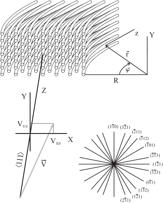
The stationary Cartesian coordinate system with axis parallel to a set of crystal axes at the crystal entrance and plane parallel to the plane of crystal bending will be used to describe the particle motion outside the crystal – see Fig. 1. However to describe the particle motion inside the latter the comoving Cartesian coordinate system (see Fig. 1) is more suitable [10]. Both the longitudinal axis and the transverse plane of this coordinate system rotate synchronously with the particle radius vector by its azimuthal angle , where is the bending radius, is the time equal zero at the crystal entrance and is the particle velocity. The dynamics of the reflection process from a ”vertical” plane is described by the effective potential , where is the radial coordinate, is the planar potential and is the particle momentum.
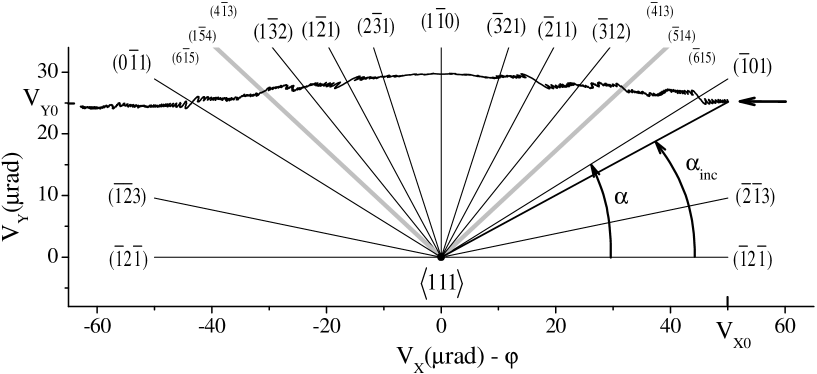
The comoving coordinate system is also suitable for treating the interaction with various crystal planes touched by particles moving at a small angle with respect to a crystal axis – see Fig. 1. With one exception all these planes are ”inclined”, i.e. form angles , , with the bending plane – see Figs 1-3. All the planes remain stationary while the horizontal velocity component (we assume that and ), on the opposite, changes with time in the transverse plane of the commoving coordinate system (see Fig. 2 ). As a result, different ”inclined” planes, one after another, become tangential to the particle velocity.
However the planes are not ”smooth”, rather consist of axes forming the angle
| (1) |
with the current particle velocity. At relatively large the maximum particle deflection angle by an axis is estimated by the formula
| (2) |
where is the total energy of a particle which is assumed to be ultrarelativistic and is an interatomic distance on the axis. A ”smooth plane” approximation in which a particle deflection by the axes does not differ considerably from that by the continuum potential of the plane constituted by these axes can be used if , where is the critical channeling angle of the considered plane set. On can make certain that the latter condition is equivalent to in the case of proton deflection by low index planes which we will consider as an example throughout the paper. The predictions made using the ”smooth plane” approximation will be checked by the direct simulations of particle motion in the field of axes in the next section. For now let us consider a particle deflection in the planar potential of an inclined bent plane.
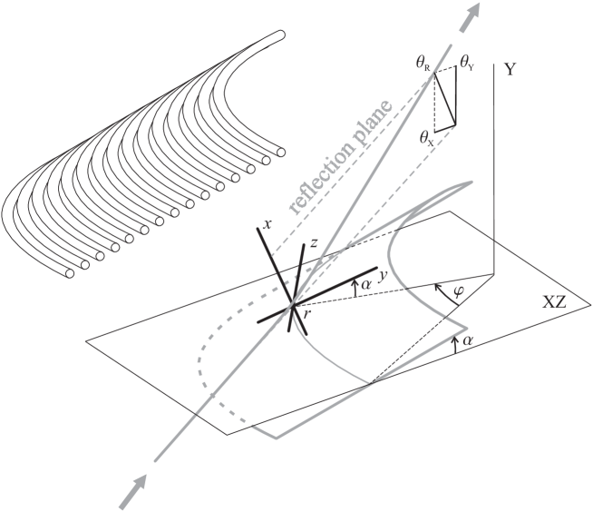
To evaluate the angle of VR from the latter we will introduce the rotated axes and being, respectively, normal and parallel to the local direction of the bent crystal plane and situated in the transverse plane – see Fig. 3. The particle motion along these axes is governed, respectively, by the effective potentials and and characterized by the modules
| (3) |
and
| (4) |
of the corresponding velocity components, where is the speed of light. The energies and of the transverse nonrelativistic particle motion in the and directions are determined by the coordinates and velocity components , at the crystal entrance. The equation
| (5) |
determines the turning point x-coordinate at a specified value. With a view to obtain explicit expressions for the particle deflection angles both in and planes we will follow [10] introducing the x-component
| (6) |
of the velocity of particle motion in the constant plane potential in the comoving coordinate system.
Since the turning point is the point of symmetry of the particle trajectory, we will, as usual [1, 10], consider only a first half of it. The auxiliary velocity -component (6) allows to write the time of particle motion from the point , , to a point , , in the form
| (7) |
where
| (8) |
Note that since the particle moves with negative velocity -component up to the turning point.
The difference of and decreases fast and, consequently, the integral (8) saturates at or at the angles of the vector rotation. Here is the planar potential amplitude which determines the critical channeling angle value. The negative integral (8) represents itself a reduction of the time of particle motion through the reflection region due to the local transverse motion acceleration in the planar potential. The time (7) which can also be expressed through the velocity y-component (4):
| (9) |
determines the angle of the local coordinate system rotation which enters the expression
for the particle velocity component along the stationary axis . The couple of expressions (7) and (9) allows to represent Eq. (10) in the form
| (10) |
Eq. (11) reduces both to the initial velocity -componrent
| (11) |
at the crystal entrance and to the expression
| (12) |
for the particle velocity X-component in the turning point in which, according to the definitions (3), (5) and (6), one has .
Applying further Eq. (13) to the intervals of particle motion before and behind the turning point one can evaluate the reflection angle at arbitrary value of the crystal bending angle , where is the crystal length. However here we will consider the most practically important case of large bending angles allowing both to neglect the difference and put in Eq. (8). Doubling then, as usual [1, 10], the deflection angle at the turning point, one finally obtains the particle deflection angle in the plane
| (13) |
where
| (14) |
is the deflection angle in the incidence plane which is parallel both to the -axis and initial particle velocity and in which the particle trajectory is situated. Eqs. (14) and (15), naturally, reduce to the expression [10] for VR angle from a ”vertical” bent plane at . Note also that the angle (14) is negative for sufficiently large bending radii at any .
In much the same way Eqs. (7) and (9) can be used to write the velocity component in the form
| (15) |
allowing to obtain the particle deflection angle in the plane
| (16) |
Eqs. (14) and (17), naturally, describe the change of transverse velocity components accompanying a mirror particle reflection from an inclined bent plane with the angle of incidence equal . In general, since the turning point coordinate is determined by Eq. (5) containing the effective bending radius , the angle (15) can not be reduced to the expression [10] for the angle of reflection from a ”vertical” bent plane by the replacement of the integration variable. Such a reduction, fortunately, becomes possible at , where is an inter-planar distance, when the angle (15) approaches the limit for infinite bending radius which does not depend on both and . In other words, the reflection angle (15) is bound from above by the same value of about [1] as that from ”vertical” plane.
3 MVR inside a crystal
The angles (14) and (17) of particle deflection from an inclined plane allow to evaluate the total angle of MVR from multiple crystal plane sets touched by a particle inside a bent crystal. An important point here is that inclined planes constitute symmetrical pairs with complimentary inclination angles and – see Figs. 1 and 2. The reflection angles (14) in the plane from such symmetrical crystal planes sum up opening a possibility to considerably increase the angle of the VR in the bending plane . On the other hand, the angles (17) of reflection in the vertical plane are opposite in sign (see Fig. 2), allowing the angle of VR in this plane to vary from several critical channeling angles down to zero. Note that significant particle deflection either in the process of MVR inside a crystal or at repetitive passages through it will violate the symmetry of particle motion in the bending plane and can cause both ”switching on” and ”off” of some crystal plane sets from the MVR process. As a consequence the latter will start giving its contribution to the particle deflection in the plane. Thus, to maintain the horizontal direction of MVR a special care in choosing crystal length, bending angle and orientation in the horizontal plane should be taken. To simplify the situation we will make here the angle of MVR in the vertical plane equal to zero restricting our consideration to the case of MVR in the crystal bending plane .
Let as consider a multiple reflection of protons from the bent crystal planes passing through the axis as an example. One of the three strongest planes passing through this axis will be directed at a right angle to the bending plane playing the role of ”vertical” plane of ”single” VR – see Figs. 1 and 2. We will also hold fixed both the crystal bending angle and symmetric direction of particle incidence in the plane (see Fig. 2) and investigate the dependence of the MVR angle on the bending radius varying the latter proportionally to the crystal length .
In order to give its contribution to MVR, a crystal plane has to have an inclination angle exceeding the angle of particle incidence with respect to the bending plane (see Fig. 2). This condition considerably limits the initial Y-component of particle velocity. In order to use the rest two strongest planes and having inclination angles and we will choose the value corresponding to . The main planes , , , , and will give their contributions to MVR at such an choice, while the planes , and will not – see Fig. 2. Note that the chosen value makes the ”smooth plane” approximation applicable, at least for the low index crystal planes.
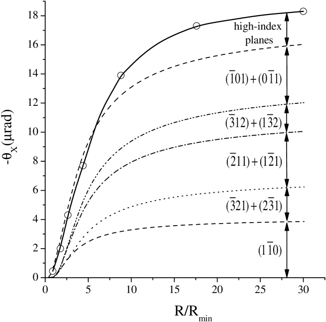
The bending radius dependence of contributions of the low-index planes to the MVR angle in the plane is illustrated by Fig. 4. The bending radius is measured in units of . Fig. 4 indeed demonstrates that an additional reflection from the inclined planes increases the total particle deflection angle about four times.
To confirm this prediction based, in fact, on the ”smooth plane” approximation direct simulations of the proton motion in the field of axes should be used. Our simulation procedure, in many respects reminding that described in [11], was considerably accelerated by the use of the approximation
| (17) |
to the potential of the axis in which , and , where is the lattice constant. This approximation allows to treat particle motion analytically both in the field of each axis and in between the neighboring axes constituting a two-dimensional hexagonal lattice in the transverse plane (see Fig. 1). These semi-analytical simulations allow to obtain such two-dimensional particle distributions in scattering angles as that shown in Fig. 5 for and .
Corresponding one-dimensional distribution in turns out to be nearly symmetric, demonstrating the absence of large coherent deflection effects in the plane predetermined by the opposite particle deflections by the paired symmetrical planes. The same situation is observed in a wide region of variation at symmetric particle incidence with in the bending plane. At some values, however, a capture into the channeling regime motion in the field of various crystal planes at the crystal entrance makes the distribution in angle strongly asymmetric even at . In general, particle capture by the numerous crystal planes at the crystal entrance, becoming possible when particles move at small angles with respect to a crystal axis, opens up other new possibilities for beam extraction and collimation which will be described elsewhere.
The distributions in angle present in Fig. 6 for several crystal bending radii confirm in general the predictions obtained in the ”smooth plane” approximation. The positions of maxima of these and several other distributions are shown by circles in Fig. 4 along with an interpolating curve. One can see that the ”smooth plane” approximation slightly overestimates the MVR angle at small and considerably underestimates it at large bending radii. In principle, the particle scattering from all the high-index planes can be additionally taken into consideration in the ”smooth plane” approximation to fill the gap between the two upper curves at large bending radii. Some of such planes, for instance, and , act coherently leading to the cumulative deflection angle distinguishable in Fig. 2. The ”smooth plane” approximation is much less applicable for these planes than for the low-index ones at the relatively small values necessary to involve more crystal planes in the MVR process in relatively short crystals. In addition, a shallow planar potential of high-index planes leads to relatively high particle volume caption probability. All these complications make a direct simulation of the particle motion in the field of crystal axes the preferred method of the MVR study. The ”smooth plane” approximation, nevertheless, gives both the simplest picture and correct intuitive estimate of the Multiple Volume Reflection effect, which can be applied for both other crystal elements and orientations as well as for the negative particle case.
For the purpose of comparison, the distribution of protons reflected from a single vertical plane bent with radius is also shown in Fig. 6 on the right. Figs. 4-6 visually demonstrate that the angles of MVR can more than four times exceed that of the ”single” VR from a ”vertical” bent plane. One can also see from Fig. 4 that the angular width of the MVR peaks exceeds that of the ”single” VR one.
The MVR distributions are also more asymmetric than the ”single” VR one. At this 10% - 15% of the protons are deflected in the direction of crystal bending acquiring a positive velocity X-component (see Figs. 5 and 6). At ”single” VR such protons amounts to 3-5% appearing because of the volume capture into the channeling regime motion due to the incoherent scattering by both electrons and nuclei. However, when particles move at small angles with respect to crystal axes constituting crystal planes, additional volume capture becomes possible due to the coherent particle scattering by separate crystal axes. Note that we have not considered the incoherent particle scattering by electrons which has to increase the particle volume caption additionally. On the one hand, the volume caption and deflection in the direction of crystal bending of ten or fifteen percent of the particles will make it more difficult to deflect the most part of them by a large angle using MVR in a long sequence of bent crystals. On the other, the increase of the mean reflection angle, of its angular dispersion and of the number of volume captured particles all add up to the broadening of the beam angular distribution. As a result, the mean square deflection angle of all the incident particles, important for efficient beam collimation [8, 9], can exceed in a 1 cm crystal in the MVR conditions.
4 Conclusions
The main idea of the paper was that particles moving at small angles with respect to a crystal axis in a bent crystal experience volume reflection from the numerous crystal planes passing through this axis. Both the newly developed model of particle reflection from inclined crystal planes and the direct simulations of particle motion in the field of crystal axes demonstrate that the total MVR angle exceeds that of the VR from a ”single” ”vertical” plane more than four times. The particle deflection angle magnification by the MVR, also used in series of parallel strip-like crystals, multiple-strip crystals, crystals periodically curved by groves or alternative tensile coating opens up new possibilities to improve the efficiency of both the beam deflection and collimation at the LHC and many other accelerators.
Acknowledgement
The author gratefully acknowledges useful discussions with V.G. Baryshevsky, X. Artru, V.A. Maisheev and I.A. Yazynin. This work was partly supported by the # 03-52-6155 INTAS Project.
References
- [1] A. M. Taratin and S. A. Vorobiev, Phys. Lett. A119 (1987) 425.
- [2] Yu.M. Ivanov et al. Phys. Rev. Lett. 97 (2006) 144801.
- [3] Yu.M. Ivanov et al. JETP Lett. 84 (2006) 372.
- [4] W. Scandale et al. Phys. Rev. Lett. 98 (2007) 154801.
- [5] V.M. Biryukov. Phys.Lett. B645 2007 47.
- [6] R.P. Fliller et al. Phys. Rev. ST Accel. Beams 9, (2002) 013501.
- [7] R.A. Carrigan et al. FERMILAB Report No. FERMILAB-CONF-06-309-AD, 2006
- [8] I.A. Yazynin. in Proceeding of the 1995 Particle Accelerator Conference (IEEE, New York, 1996), Vol. 3, pp.1952-1954.
- [9] V.M. Biryukov. physics/0609214.
- [10] V.A. Maisheev. physics/0607009.
- [11] A.I. Akhiezer, N.F. Shulga, V.I. Truten, A.A. Grinenko and V.V. Syshchenko. Phys. Usp. 38 (1995) 1119.