Magnetic fields above the surface of a superconductor with internal magnetism
Abstract
The author presents a method for calculating the magnetic fields near a planar surface of a superconductor with a given intrinsic magnetization in the London limit. He computes solutions for various magnetic domain boundary configurations and derives relations between the spectral densities of the magnetization and the resulting field in the vacuum half space, which are useful if the magnetization can be considered as a statistical quantity and its features are too small to be resolved individually. The results are useful for analyzing and designing magnetic scanning experiments. Application to existing data from such experiments on Sr2RuO4 show that a domain wall would have been detectable, but the magnetic field of randomly oriented small domains and small defects may have been smaller than the experimental noise level.
pacs:
74.25.Ha, 74.20.De, 75.70.-i, 74.70.PqI Introduction
Starting with the discovery of ferromagnetic order in the superconductors HoMo6S8 Lynn et al. (1978); Ishikawa and Fischer (1977) and ErRh4B4Fertig et al. (1977) about three decades ago, there has been increasing interest in superconductors with an intrinsic magnetization. In the above cases and some of the RNi2B2C compounds (R = rare earth), the magnetization is due to localized moments of the rare earth ions and coexists with superconductivity in some temperature range. In other materials, the conduction electrons may not only superconduct, but also carry some magnetization. A prominent example is Sr2RuO4 Maeno et al. (1994), which is believed to have a complex, time reversal symmetry breaking -wave order parameter, Mackenzie and Maeno (2003) so that the orbital angular momentum of the Cooper pairs creates a magnetic moment. This is theoretically expected to cause edge currents at sample boundaries and domain walls.Matsumoto and Sigrist (1999); Sigrist et al. (1989) A similar effect has been suggested to occur in the -wave superconductor NaxCoOH2O.Baskaran (2003)
The traditional experimental techniques for studying magnetic ordering phenomena are bulk probes such as muon spin rotation (SR) or (spin polarized) small angle neutron scattering (SANS). An alternative approach is to use magnetic scanning techniques such scanning Hall probe microscopy (SHPM), Chang et al. (1992) scanning SQUID microscopy,Kirtley and Wikswo (1999) magnetic force microscopy (MFM) Rugar et al. (1990); Moser et al. (1995) and magneto-optical techniques.Koblischka and Wijngaarden (1995) These techniques measure the magnetic field some small distance above the surface of the sample as a function of position. In many cases, their resolution, which is limited by the probe size and probe–sample distance, does not quite reach the length scales typical for the magnetic structure. For example, one finds evidence for oscillatory magnetic order with a sub-penetration depth length scale in HoMo6S8 Lynn et al. (1978); Ishikawa and Fischer (1977) and ErRh4B4.Fertig et al. (1977) For larger wave lengths, the Meissner effect in the coexisting state would screen the field and thus suppress magnetic interactions and destabilize the magnetic order. A similar situation has been observed in the superconductor ErNi2B2C using SHPM.Bluhm et al. (2006) The direct observation of the magnetic fields generated by edge currents or domain walls in Sr2RuO4 is an ongoing effort which has not produced any evidence so farBjornsson et al. (2005); Kirtley et al. (2007).
To plan such scanning experiments and to interpret the resulting data, it is important to understand to what extent the magnetic field generated by a spatially varying magnetization inside the sample is propagated to the probe. In normal materials, this is a straightforward magnetostatics problem. In superconducting samples, however, it is complicated by the Meissner screening. In this work, I present solutions for an infinite planar sample surface by incorporating the presence of a magnetization into a London model and solving the resulting equations, using a 2D Fourier transform. This approach follows earlier theoretical work on superconductors with an internal magnetization due to localized magnetic moments, Greenside et al. (1981); Blount and Varma (1979); Ng and Varma (1997); Kuper et al. (1980) but should also apply if the magnetism is of different origin, such as a spin or orbital moment of the Cooper pairs. To consider the practically very likely case where the limited measurement resolution leads to significant averaging over several domains or other features with some degree of randomness, I present a spectral analysis. The resulting relations were employed for the analysis of the data in Ref. Bluhm et al., 2006 and may also be used to analyze null results where no field variation is detectable at the experimental noise level. A similar analysis may also be useful for interpreting surface sensitive SR experiments, which only average over a thin layer at the sample surface Morenzoni et al. (2004).
The paper is organized as follows: In section II, I derive the main equations of our model from a generalized Ginzburg-Landau (GL) functional. Those equations are solved in a general framework in section III. In section IV, I discuss simple domain wall and dipole configurations as examples. Relations between the spectral densities of the magnetization and the magnetic field in vacuum are computed in section V. Section VI applies the results to recent magnetic scanning work Bjornsson et al. (2005) on Sr2RuO4.
II Model
In order to fully describe the interplay between magnetism and superconductivity in a phenomenological approach, the magnetization and the superconducting order parameter have to be computed self consistently, taking mutual interactions into account. This has been done in Refs. Greenside et al., 1981; Blount and Varma, 1979; Ng and Varma, 1997; Kuper et al., 1980 using the generalized GL functional
| (1) | |||||
where . In this work, I will assume this task to be partially solved by starting with a given and computing the resulting magnetic field, taking shielding currents into account. This approach is clearly justified if the magnetic energy scale is much larger than the superconducting one, so that the effect of superconductivity on magnetism can be neglected. However, it is also reasonable if the result of a self consistent calculation for is (approximately) known, for example from bulk calculations, and one is mainly concerned with the effect of the reduced screening at the surface on the observable field. The errors introduced by this treatment will then primarily be due to the effect of the surface and the modified screening on .
Writing the order parameter as and introducing the London penetration depth defined by , variation of Eq. (1) with respect to leads to
By performing a line integral over a closed loop after multiplying by and using the Stokes theorem, one obtains
| (2) |
is a sum of 2D - functions representing vortex cores, which will be ignored in the following. This result can be obtained directly by treating the supercurrent density as macroscopic current in the macroscopic Maxwell equation and thus substituting into the London equation . Although the above is valid for a spatially varying superfluid density , I will assume to be constant, which leads to the more familiar form
| (3) |
I assume the magnetic superconductor to occupy the lower half space . In vacuum (), the magnetic field must satisfy and . At the interface, the normal component of and the tangential component of must be continuous. Note that enters Eq. 3 only through the microscopic current density . Thus, one may also start directly from an intrinsic current density rather than , which is more natural if an edge current is known from microscopic calculations, for example. The appearance of in the tangential boundary condition can also be eliminated by replacing it with a discontinuity in just below the surface.
III Solution
In Ref. Kogan et al., 1993, the field geometry of a vortex penetrating the surface of an anisotropic superconductor for a general orientation of the vortex and the main axis of the effective mass tensor with respect to the interface has been computed. In the vortex problem, the right hand side appearing in the London equation Eq. (3) is a 2D delta function instead of the magnetization term. I use the same technique, but only present the calculations for the isotropic case for the sake of simplicity.
The Maxwell equations in vacuum can be satisfied by writing the magnetic field as with . A suitable solution has to be matched to a solution of Eq. (3) at z = 0. I solve this problem using a 2D Fourier transform (FT) in the -plane, i.e. by writing a function as , with and . (Note that I use the same symbol for 2 and 3 dimensional vectors, implying that the - component vanishes for the latter.) For , the field is decomposed as + . is a particular solution of the inhomogeneous London equation (3) in full space with boundary conditions at infinity and with the right hand side suitably extended to . is a general homogeneous solution chosen to satisfy the matching condition at the interface. Under the 2D FT, Eq. (3) transforms into , so that with . In vacuum, has the solutions so that at , .
Hence, together with the , and components of the continuity conditions for and at read
The last equation for the in-plane transverse component of is already decoupled and can be dropped if only the vacuum field is to be computed. Solving the first three equations for leads to
| (4) |
If the 2D FT of the inhomogeneous solution, , cannot be obtained directly, the 3D FT of can be obtained from by solving the linear system
The solenoidal condition will always hold as . The 2D FT at is then simply with . While this approach to the inhomogeneous problem is very convenient for numerical evaluation and can be generalized to the anisotropic case (cf. Ref. Kogan et al., 1993), it is useful to derive an explicit solution. The component of parallel to does not contribute to . For components of and orthogonal to , automatically and the vector products simplify to scalar multiplication. By decomposing and into components along the unit vectors orthogonal to in the -plane and , the inhomogeneous solution thus simplifies to
| (5) |
To evaluate Eq. (4), the inverse z-FT must be carried out in order to obtain the values at , unless is - independent. It turns out that does not enter Eq. (4) because of the dot product with . Projecting onto the and direction, substituting Eq. (III), and expressing everything in terms of and using leads to
| (6) |
The terms in the numerator of the fractions can be dropped if one uses the convention that is extended to as an even function so that those terms do not contribute to the integrals. Eq. (6) can be summarized qualitatively as follows: For in-plane components of , the source of outside the superconductor is the divergence of averaged over one penetration depth below the surface. For the normal component, an additional derivative is taken, thus increasing the multipole order of the vacuum field by one. The small components of the field are just those resulting from the subsurface magnetization and its image obtained by reflection about a plane below the surface.
I would like to point out that for the solution method to work as described, the interface must be planar and should be constant. on the contrary can be an arbitrary function. However, if so that solves Eq. (2), the requirement that may not depend on can be dropped at the expense of solving a more complicated ordinary differential equation instead of the Laplace equation to obtain . For example, discontinuities in as a function of could be treated by matching additional continuity conditions. A dependence of on or on the other hand would mix different components and thus generally forbid a simple analytic solution.
IV Examples
IV.1 Discussion of Table 1
As examples for various simple, representative configurations in , I have calculated the field of ferromagnetic domain walls, where changes sign, and dipoles at the surface. For , simple approximate expressions in real space can be obtained. The results are shown in table 1. The approximations are based on the fact that for , only contributes to the Fourier integral . To second order, and . Thus, the approximations in table 1 are good to three and two orders beyond leading order in for cases (1),(3) and (2), (4), respectively. In the following, I discuss the far fields obtained from these approximations. To understand those, it is useful to recall that for magnetostatic problems in the absence of macroscopic or supercurrents, . Thus, acts as a magnetic charge by analogy with electrostatics. The field of a discontinuity of the in-plane component of [case (1)] is just twice that of a magnetically charged line with linear charge density situated below the surface. It can be understood as the charge density due to the discontinuity of in the magnetization, which is screened by supercurrents over one penetration depth. The additional factor two formally comes from the extension of to . For a discontinuity in the normal component [case (2)], one obtains the dipole field of two lines of opposite magnetic charge with a charge density as above and a separation of . Again, this can be understood as the screened field of the discontinuity in the magnetization occurring at the surface.
The localized dipole pointing into or out of the surface [case (3)] has a a quadrupole field. An in-plane moment [case (4)] on the contrary has a dipole field to leading order. For a dipole chain, i.e. , I obtain the same results as for a single dipole oriented in the direction [case (3)] with . The same analogy can be drawn for case (4).
It is also of interest to consider a configuration where a magnetization is localized over a width around . This situation may be encountered at an antiferromagnetic domain wall, where canting of antiferromagnetically ordered in-plane moments produces a local net out-of-plane magnetization. The corresponding exact solution is a superposition of two solutions for normal discontinuities with opposite signs, shifted by . If is smaller than all other length scales, can be replaced by a delta function: . The resulting field is then simply the derivative of that of a discontinuity in , i.e. for ,
| Case | (exact) | (approximate) | |
|---|---|---|---|
| (0) | 0 | 0 | |
| (1) | |||
| (2) | |||
| (3) | |||
| (4) |
IV.2 Periodic configurations
If the magnetization is periodic, the Fourier integrals turn into Fourier sums. If the period is large (), features with size comparable to can be resolved in each unit cell individually and look similar to a solution obtained from a constant continuation of outside that cell. For shorter periods however, the superposition of many such single cell solutions largely cancels out. Formally, this follows from the fact that the wave vector takes only integer multiples of . Therefore, the dominant contributions at considered in table 1 are not present an the leading term becomes that of the lowest wave vector . This results in an exponential suppression by of the lowest harmonic of the field variation at a height above the surface and all higher harmonics being negligible for .
IV.3 Effect of smoothing
As the exponential cutoff in the inverse FT becomes increasingly sharper for larger , the far field from any feature of finite size in the magnetization will always be determined by the lowest non-vanishing power of in for sufficiently large . For a smooth domain wall, has less weight at large compared to a sharp discontinuity of equal magnitude, but the values at small are affected little. Thus, the asymptotic results for sharp discontinuities in are still valid if changes smoothly over a width as long as . For example, the far field of a single domain boundary does not depend on the length scale over which the magnetization changes in the -plane, but only on the difference between the asymptotic values of on both sides. Hence, the approximate results in table 1 are of rather general validity. For a graphic illustration, see Fig. 2, which is discussed in Sec. VI. The situation is slightly different for a nontrivial -dependence of : the -cutoff is always determined by the factor for small . In real space, this corresponds to an exponentially weighted average over a distance of below the surface.
V Spectral Analysis
The resolution of currently available magnetic imaging techniques is often not sufficient to resolve an actual domain structure. In practice, averaging occurs both due to the imaging height and the finite sensor size. Here, I will only consider the more universal height effect. For a height larger than the typical domain size, the magnetic field represents an average over several domains. As shown in the previous section, this would lead to an exponential suppression for periodic configurations. However, domains will usually not be strictly periodic, but have some distribution of size. Therefore, a statistical description is most adequate. Assuming a given correlation function and thus spectrum of the magnetization , I compute the spectrum of the resulting magnetic field.
The spectral function of two functions and in dimensions, , satisfies the relation Here, stands for an ensemble average over different realizations of and . It is implicit to this definition that the correlator is independent of .
It is convenient to introduce the propagation coefficients
| (7) | |||||
| (8) |
and rewrite Eq. (6), using , as . It follows that
| (10) |
I have used as a short hand notation for the spectral function of two different components of . Similar expressions can be written down for spectral densities involving other components of .
Because of the presence of the surface, the assumption of translational invariance in the -direction implicit to the definition of is by no means trivial. If the presence of the surface does not affect the structure of too much, and the range of the surface influence is much shorter than , most of it should average out because is sensitive to what happens within a layer of thickness below the surface. However, the -invariance is only required in order to define spectral functions . If the interface (or other effects) do break the -invariance of so that it depends on both and , it is still possible to derive an expression for similar to Eq. (V), however involving a double integral over .
A statistical analysis will be most relevant when the measurement height is much larger than any of the intrinsic length scales of the variation of , i.e. too large to resolve individual features. In this case, will not have a strong dependence in the small region surviving the cutoff and can be approximated by . For , a similar approximation can be made for the propagation coefficients and :
| (11) | |||||
| (12) |
In any case, the properties of only enter via the integrals
| (13) |
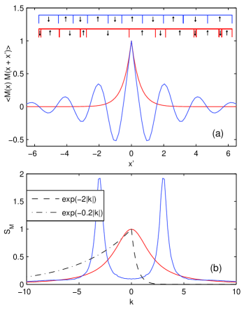
As argued above, it will often be a good approximation to set . In many cases, will have a peak at some wave vector (and consequently at ), similar to the illustration in Fig. 1. For simplicity, I assume that there is only one such maximum. A finite is a signature of an oscillatory behavior of . The width of the peak corresponds to the inverse coherence length of the oscillation or the correlation length for .
The integral (13) can be approximated further in two limiting cases. If the coherence length of along the direction is much larger than , then is sharply peaked, and the kernel can be replaced by and pulled out of the integral. In the opposite limit, the peak in is much wider than so that the dependence of can be neglected entirely and one obtains
Assuming that the -component of dominates, the respective diagonal term of Eq. (V) takes the form
for . If the component is dominant, in the prefactor must be replaced by . Similar expressions can be written down for the off-diagonal components of . For an illustration of the relation between a measured and its spectral function, the reader is referred to Ref. Bluhm et al., 2006. Integration leads to simple expressions for :
| (14) | |||||
| (15) |
Those expressions can be used to estimate the signal expected in a scanning experiment or to estimate from the observed field variation. Note that if the variation of the domain size is sufficiently large for to be essentially non-negative, as for the exponential width distribution in Fig. 1, can be interpreted as the product of a correlation volume and the mean square magnetization .
VI Application to Sr2RuO4
Based on various evidence, it is believed that Sr2RuO4 is a spin triplet superconductor with a -wave order parameter of the same symmetry class as .Mackenzie and Maeno (2003); Nelson et al. (2004) Convincing evidence that the order parameter is indeed time-reversal symmetry breaking (TRSB) has recently been obtained by Sagnac-interferometry experiments.Xia et al. (2006) Such a TRSB order parameter is expected to cause chiral currents at sample edges, domain walls or impurities. Matsumoto and Sigrist (1999); Sigrist et al. (1989) The direct observation of such effects in Sr2RuO4 is an ongoing effort. So far, the most direct indication of spontaneous fields is given by SR data, reporting “a broad distribution of fields arising from a dilute distribution of sources”.Luke et al. (1998) Phase sensitive tunneling measurements support the notion of small chiral domains.Kidwingira et al. (2006) Scanning Hall probe and scanning SQUID microscopy experiments Bjornsson et al. (2005); Kirtley et al. (2007); Dolocan et al. (2005) on the other hand did not detect any sign of a spontaneous magnetization associated with superconductivity.
The magnetic scans of the -face in Ref. Bjornsson et al., 2005 showed neither localized features nor a random field variation that could be attributed to TRSB. Even holes that were drilled using a focused ion beam (FIB) failed to show a magnetic signature. Lacking suitable theoretical models, a quantitative analysis of those null results was inconclusive. In this section, I will use the results derived above to compute the expected field from domains and defects. This allows to set certain limits on the internal magnetization strength that would be consistent with the data.
A complete description of chiral domains requires a self consistent computation of the order parameter and magnetic fields. This has been carried out using microscopic theory Matsumoto and Sigrist (1999) and a GL approachSigrist et al. (1989) without considering the effect of a surface. Such detailed calculations generally require a numerical solution. Taking the presence of a surface into account leads to a further complication. Thus, they are rather cumbersome for the purpose of data analysis and planning experiments.
For a domain wall along the plane in an infinite sample, the results of those computations generally show a current along the -direction which decays over about one in-plane coherence length in the -direction and changes sign. The counterflowing current decays on the scale of such that the magnetic field far inside each domain vanishes. Indeed, one can obtain good fits of the form
| (16) |
to the numerical results for the magnetic field of Ref. Matsumoto and Sigrist, 1999, with , , and G. I used = 66 nm and = 150 nm Mackenzie and Maeno (2003) to compute the thermodynamic critical field entering the prefactor of the result of Ref. Matsumoto and Sigrist, 1999. It is easy to show that this expression is a solution to the London equations for in the presence of a chiral current density . This current can be identified with an internal magnetization in the direction due to the orbital magnetic moments of the Cooper pairs. The value of is in good agreement with the value of assumed in Ref. Matsumoto and Sigrist, 1999. This suggests that the London approach captures screening effects quite accurately, and therefore should give a good approximation for the field above a surface. Of course, this will neglect some features in the full GL solutions. For example, the latter show a slight depression of the superfluid density near the domain wall, which is neglected here by assuming a constant . Similar modifications of both the superfluid density and the chiral current density at the surface should be small due to the short -axis coherence length . The anisotropy is of no consequence because all currents flow along the -plane so that only matters.
Since the far field of the domain wall only depends on the difference of the asymptotic values of away from the domain wall, and experimentally m, it is appropriate to use the large- results for a sharp discontinuity in to analyze the results of Ref. Bjornsson et al., 2005. If accurate results at a are required, Eq. (4) together with the above approximation for should be used. Fig. 2 shows the field profiles for those two methods and the exact result for a sharp domain wall at different heights.
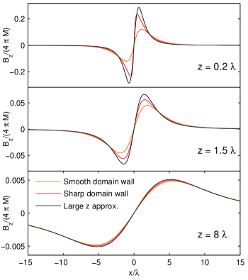
In the experiments, the rms noise levels were 35 mG and 0.45 mG at imaging heights m and 2 m in the Hall probe and SQUID scans, respectively. Correction factors due to oversampling and averaging over the size of the SQUID pickup loop are of order unity. An isolated domain wall would result in a field of G and G respectively at the above imaging heights and G, and should be clearly visible in the data. Thus, there was either no such domain wall in the scanned area, or its magnetization was G and G respectively, so that it was hidden by sensor noise.
The exact calculation of the signature of a hole is more difficult because the translational invariance of the boundary conditions is broken. However, if the diameter of the hole or defect, which I assume to extend along the -direction normal to the surface, is much smaller than , the absence of superfluid in it can be neglected and the dipole calculation should be a good approximation. For a hole or defect with a volume of , the maximum field according to case (3) in table 1 at m and 2 m is mG and mG, respectively. This signal would be nearly undetectable at the experimental noise level of Ref. Bjornsson et al., 2005. Furthermore, the extent of the defect along the -direction could be as small as , and the order parameter is not necessarily suppressed entirely. For a columnar defect on the other hand, one factor of has to be replaced by , decreasing the limit on only by about a factor three. Since the FIB drilled holes in the experiment were significantly larger (about 1 m), they have both a larger moment and less effective Meissner screening. This leads to a stronger signal whose calculation goes beyond the scope of this paper.
One can also estimate the signal expected from a random configuration of small domains. The smallest conceivable domain volume is on the order of . Assuming that the domain size fluctuates enough to use this as correlation volume, Eq. (15) implies that the rms signal could be as small as 0.7 mG and 0.16 mG, again less than the experimental noise. A domain size distribution that does not satisfy the assumptions leading to Eq. (15) may result in even smaller signals. Thus, the possibility of very small domains cannot be ruled out.
In all the above cases, the smaller imaging height of the Hall probe does not compensate for its large noise compared to the SQUID. Assuming the predicted magnitude of the chiral currents Matsumoto and Sigrist (1999) is correct, the calculations show that any domain wall should have been detected by the measurements. Small defects on the other hand might easily have been hidden in the noise. It is also possible that a random signal from domains would have been too small to observe, especially if the domains are short in the -direction or very homogeneous in size while not too large. However, it appears that one should not take the notion of a magnetization due to -wave pairing too literally. It was shown Braude and Sonin (2006) that the chiral currents can in general not be written as the curl of a global magnetization, and that the effective value of depends on the type of domain wall.
VII Conclusion
I have presented a model for a superconductor with an intrinsic magnetization by combining the macroscopic magnetostatic Maxwell equation with the London relation and obtained the field geometry at a planar superconductor-vacuum interface for a given spatial variation of the magnetization. Solutions for a range of specific magnetic domain boundary configurations give simple expressions in the limit of a large height above the sample. If the height above the surface at which the magnetic field can be measured exceeds the characteristic length scale of variations in the magnetization, a spectral analysis can be used to relate the spectral densities of the two at resolvable wave vectors. If a specific model for the structure of the magnetization is at hand, a direct comparison with the measured field is possible. Otherwise, some simplifying assumptions give a simple estimate relating the spectral density of at the superconductor - vacuum interface to the observable spatial rms-variation of the magnetic field. As an example for an application, I have applied my calculations to recent experimental results on Sr2RuO4Bjornsson et al. (2005), concluding that large chiral domains would have been visible in those experiments, but small domains and defects may have escaped detection.
Acknowledgements.
I would like to thank Kam Moler, Ophir Auslaender and John Kirtley for giving feedback on the manuscript. This work has been supported by the Department of Energy under contract DE-AC02-76SF00515.References
- Lynn et al. (1978) J. W. Lynn, D. E. Moncton, W. Thomlinson, G. Shirane, and R. N. Shelton, Solid State Commun. 26, 493 (1978).
- Ishikawa and Fischer (1977) M. Ishikawa and O. Fischer, Solid State Commun. 23, 37 (1977).
- Fertig et al. (1977) W. A. Fertig, D. C. Johnston, L. E. DeLong, R. W. McCallum, M. B. Maple, and B. T. Matthias, Phys. Rev. Lett. 38, 987 (1977).
- Maeno et al. (1994) Y. Maeno, H. Hashimoto, K. Yoshida, S. Nishizaki, T. Fujita, J. G. Bednorz, and F. Lichtenberg, Nature (London) 372, 532 (1994).
- Mackenzie and Maeno (2003) A. P. Mackenzie and Y. Maeno, Rev. Mod. Phys. 75, 657 (2003), and references therein.
- Matsumoto and Sigrist (1999) M. Matsumoto and M. Sigrist, J. Phys. Soc. J. 68, 994 (1999), see also erratum in Vol. 68, p. 3120.
- Sigrist et al. (1989) M. Sigrist, T. M. Rice, and K. Ueda, Phys. Rev. Lett. 63, 1727 (1989).
- Baskaran (2003) G. Baskaran, Phys. Rev. Lett. 91, 097003 (2003).
- Chang et al. (1992) A. M. Chang, H. D. Hallen, L. Harriott, H. F. Hess, H. L. Kao, J. Kwo, R. E. Miller, R. Wolfe, J. Vanderziel, and T. Y. Chang, Applied Physics Letters 61, 1974 (1992).
- Kirtley and Wikswo (1999) J. R. Kirtley and J. P. Wikswo, Annual Review of Materials Science 29, 117 (1999).
- Rugar et al. (1990) D. Rugar, H. J. Mamin, P. Guethner, S. E. Lambert, J. E. Stern, I. McFadyen, and T. Yogi, J. Appl. Phys. 68, 1169 (1990).
- Moser et al. (1995) A. Moser, H. J. Hug, I. Parashikov, B. Stiefel, O. Fritz, H. Thomas, A. Baratoff, H. J. Guntherodt, and P. Chaudhari, Phys. Rev. Lett. 74, 1847 (1995).
- Koblischka and Wijngaarden (1995) M. R. Koblischka and R. J. Wijngaarden, Superconductor Science & Technology 8, 199 (1995).
- Bluhm et al. (2006) H. Bluhm, S. E. Sebastian, J. W. Guikema, I. R. Fisher, and K. A. Moler, Phys. Rev. B 73, 14514 (2006).
- Bjornsson et al. (2005) P. G. Bjornsson, Y. Maeno, M. E. Huber, and K. A. Moler, Phys. Rev. B 72, 012504 (2005).
- Kirtley et al. (2007) J. Kirtley, C. Kallin, C. Hicks, E.-A. Kim, Y. Liu, K. Moler, Y. Maeno, and K. Nelson, arXiv:0704.3364v1 [cond-mat.supr-con] (2007), (unpublished).
- Greenside et al. (1981) H. S. Greenside, E. I. Blount, and C. M. Varma, Phys. Rev. Lett. 46, 49 (1981).
- Blount and Varma (1979) E. I. Blount and C. M. Varma, Phys. Rev. Lett. 42, 1079 (1979).
- Ng and Varma (1997) T. K. Ng and C. M. Varma, Phys. Rev. Lett. 78, 330 (1997).
- Kuper et al. (1980) C. G. Kuper, M. Revzen, and A. Ron, Phys. Rev. Lett. 44, 1545 (1980).
- Morenzoni et al. (2004) E. Morenzoni, T. Prokscha, A. Suter, H. Luetkens, and R. Khasanov, J. Phys. Cond. Mat. 16, S4583 (2004).
- Kogan et al. (1993) V. G. Kogan, A. Y. Simonov, and M. Ledvij, Phys. Rev. B 48, 392 (1993).
- Nelson et al. (2004) K. D. Nelson, Z. Q. Mao, Y. Maeno, and Y. Liu, Science 306, 1151 (2004).
- Xia et al. (2006) J. Xia, Y. Maeno, P. T. Beyersdorf, M. M. Fejer, and A. Kapitulnik, Phys. Rev. Lett. 97, 167002 (2006).
- Luke et al. (1998) G. M. Luke, Y. Fudamoto, K. M. Kojima, M. I. Larkin, J. Merrin, B. Nachumi, Y. J. Uemura, Y. Maeno, Z. Q. Mao, Y. Mori, et al., Nature 394, 558 (1998).
- Kidwingira et al. (2006) F. Kidwingira, J. D. Strand, D. J. V. Harlingen, and Y. Maeno, Science 314, 1267 (2006).
- Dolocan et al. (2005) V. O. Dolocan, C. Veauvy, F. Servant, P. Lejay, K. Hasselbach, Y. Liu, and D. Mailly, Phys. Rev. Lett. 95, 097004 (2005).
- Braude and Sonin (2006) V. Braude and E. B. Sonin, Phys. Rev. B 74, 64501 (2006).