A small tabletop experiment for a direct measurement of the speed of light
Abstract
A small tabletop experiment for a direct measurement of the speed of light to an accuracy of few percent is described. The experiment is accessible to a wide spectrum of undergraduate students, in particular to students not majoring in science or engineering. The experiment may further include a measurement of the index of refraction of a sample. Details of the setup and equipment are given. Results and limitations of the experiment are analyzed, partly based on our experience in employing the experiment in our student laboratories. Safety considerations are also discussed.
I Introduction
The speed of light is a basic physics quantity of importance in many areas of physics, be it astrophysics or relativity. Therefore, it is highly desirable to have an experiment to measure the speed of light that is easy to set up and any student can perform. In this note, we provide details of an experiment for directly measuring the speed of light in air. This small tabletop experiment can be performed quite satisfactorily by undergraduate students, including non-science or non-engineering majors and perhaps also by high school students. The principle of the experiment dates back at least a few hundred years to that of Galileo. We obtain the speed of light from the time of flight, essentially by measuring the time the light takes to travel a certain distance and back. The experiment utilizes a pulsed laser and an oscilloscope to measure the time of flight.
The requirements for our experiment were as follows:
-
•
The concept of the experiment is quite comprehensible to non-science and non-engineering majors.
-
•
The optical path is in air and is visible.
-
•
The experiment can be performed on a tabletop.
-
•
The students are able to safely conduct the experiment without difficulty.
-
•
The measurement is reasonably accurate, but does not sacrifice clarity for precision.
-
•
The cost of the experimental setup is inexpensive.
We have been able to satisfy all the requirements above. To our knowledge, standard experimental textbooks do not contain expositions of an experiment such as ours. Many experiments to measure the speed of light have been presented, including a number of interesting time of flight measurementsCooke68 ; Tyler69 ; Van73 ; Crandall82 ; Becc87 ; Deb91 ; James99 . However, we could not find any that satisfied all the requirements. In particular, most of the simpler experiments require a large space, which we can not afford.
The purpose of this note is pragmatic: Our objective is to provide the details of the experiment to a wide audience, so that it can be performed at other institutions, if so desired. The electronic part of the experiment is original and we provide its full details below. The components needed to build the light source and the detector are quite inexpensive. Experiments that are different, but similar in spirit, seem to be performed at other institutionsSakurai ; tohoku ; shimadzu .
II Details of the experiment
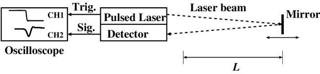
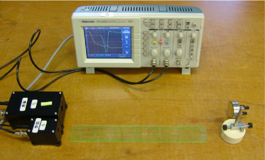
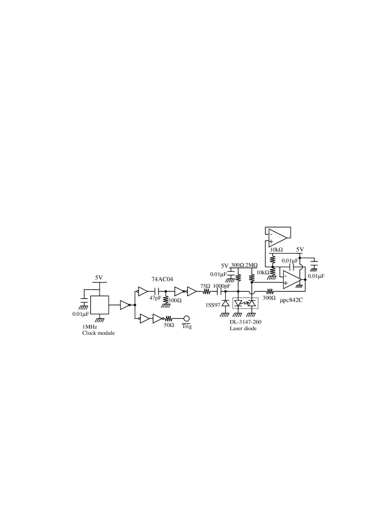
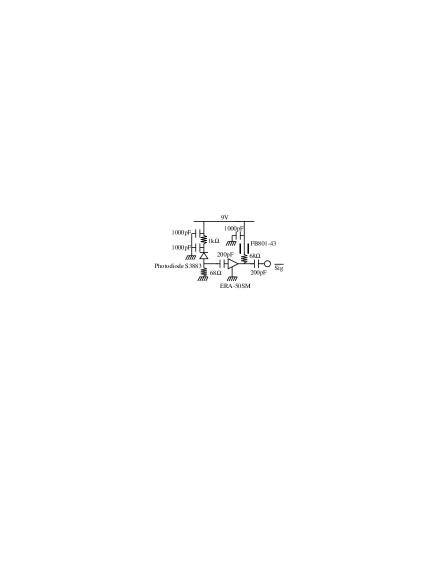
The basic experimental setup is simple and is shown in Fig. 1 and Fig. 2. Pulsed laser is reflected off a mirror and is detected by a photodiode. An oscilloscope is used to obtain the time of flight , where is the (one way) length of the path. The circuits for the pulsed laser and the detector are shown in Fig. 3 and Fig. 4. The pulsed laser has a quartz generated pulse modulation frequency of 1.0 MHz, wavelength 650 nm and an average optical output of 30 W (30 pJ/pulse). We have used a 200 MHz oscilloscope with 2 GHz sampling (Tektronix TDS2022). Such oscilloscopes are now quite standard and are affordable, especially considering that they can be used for various purposes. An example of the observed signal is shown in Fig. 5. The total space required by the experimental equipment is about 1.5 m by 0.5 m.

To be concrete, we outline the procedure in our student experiments, which we have found to be quite effective, as an example. We let the students measure the difference in the time of flight, , at various , from a reference value. (We use m from the reference point.) Then the students plot the data points and fit a straight line to them to obtain the speed of light. Some reasons we have chosen this procedure is as follows:
-
•
By measuring the delay caused by light transmission for various , it is difficult for students to miss the meaning of the finiteness of the speed of light.
-
•
Taking multiple measurements not only increases accuracy but decreases the probability of simple errors.
We remark here that using lengths such as m lead to values which are quite close to round numbers. This tends to mislead the students into thinking that the speed of light measurement has unreasonably small experimental errors, since the students tend to obtain m/s as a result which differs from the precise value only by 0.1 %.
The dominant source of error in the experiment is the measurement of the time interval, . With a 200 MHz oscilloscope we use, error in the time interval ns. With m and ns, the relative error in the velocity of light is 3%. The error can be reduced by using larger or a faster oscilloscope. Also, using a slower oscilloscope such as one at 100 MHz increases the experimental error with the same distance. A systematic error is introduced by approximating the path length by without taking into account the lateral shift in the beam. While the correction can be incorporated, its relative contribution is at a few times level. Overall, we find the precision of this experiment to be quite satisfactory for our purposes.
We briefly explain an extension of the experiment which we also perform. By including some refractive material in the optical path, we can measure its index of refraction from the time delay, , using the equation
| (1) |
Here, is the physical length of the refractive material in the optical path. We have used an acrylic rod of m, which has an index of refraction, . The relative error in is 20 % (for m), so that the absolute error in the index of refraction for our setup is . This is not so accurate, but is quite sufficient for our purposes, which is to see that having an index of refraction larger than one is equivalent to having a slower speed of light and to obtain the approximate value of the index. Since the light is attenuated by the refractive material, it is more difficult to pick up the signal, but students can do so with a little effort. This part of the experiment is easier to perform without a mirror.
Let us comment on the safety aspects regarding the laser beam: The average power of the laser light is W. The measured pulse width is 2.5 ns. This is an upper bound since the high frequency measurement can be limited by the performance of the oscilloscope itself. While it is ill–advised to observe the laser light without safety glasses, the laser beam does not seem to necessitate such safety precautions at this timeHS04 . The laser circuit (Fig. 3) is designed containing a feedback circuit to keep the average light output constant. The average output was chosen to satisfy the following two competing conditions: From safety considerations, we would like the output to be small. However, we also would like the beam to be strong enough and visible so that the experiment can be performed with ease. Our choice seems to satisfy both these conditions, as explained above. The pulse modulation frequency was chosen to obtain the desired light output.
III Discussion
We have explained concretely how to realize a small tabletop experiment to measure the speed of light to a few percent level. The error can be easily brought down to a percent level if we allow ourselves to use a path length of few meters, instead of one as was done above. To achieve such accuracy, the quality of the signal and the detector was crucial and the required electronics has been explicitly described above. We have adopted this experiment, including the index of refraction measurement, in our classes and roughly 600 students majoring in humanities and social sciences (mostly freshmen) at Keio University have performed it. The experiments have been conducted essentially with no problems and the results are quite satisfactory. The experiment is done in groups of one or two students each, in a three hour session. This includes the time for explanation by the lecturer and the time to write a short report on the experiment. The concept of the experiment is easily grasped by non-science/engineering majors. Furthermore, the experimental output tends to lead to a good understanding of the finiteness of speed of light, which is otherwise not easy to experience directly. Most students achieve the kind of experimental accuracy as designed. Also, using refractive material, the students can really see and understand that the refractive material “slows the light down”. For most non-science/engineering students, it is the first (and maybe the last) time for them to handle an oscilloscope and this technical aspect is probably the most difficult part of the experiment. Most students seem to understand and enjoy the visualization of the signal provided by the oscilloscope. Other than some instructions on the usage of the oscilloscope, the experiment can be performed independently by students in most cases.
Acknowledgements: This work was supported in part by the grants from Keio University and the Ministry of Education, Culture, Sports, Science and Technology of Japan.
References
- (1) J. Cooke, M. Martin, . McCartney and H. Wilf, “Direct determination of the speed of light as a general physics laboratory experiment”, Am. J. Phys. 36, 847 (1968).
- (2) C.E. Tyler, “A pedagogical Measurement of the velocity of light”, Am. J. Phys. 49, 740–745 (1969).
- (3) J. Vanderkooy and M.J. Beccario, “An inexpensive, accurate laboratory determination of the velocity of light”, Am. J. Phys. 41, 272–275 (1973).
- (4) R. E. Crandall, “Minimal apparatus for the speed of light measurement”, Am. J. Phys. 50(12), 1157–1159 (1982).
- (5) F. D. Becchetti, K. C. Harvey, B. J. Schwartz, and M. L. Shapiro, “Time of flight measurement of the speed of light using a laser and a low-voltage Pockels-cell modulator”, Am. J. Phys. 55(7), 632–634 (1984).
- (6) J. A. Deblaquiere, K. C. Harvey, and A. K. Hemann, “Time of flight measurement of the speed of light using an acousto-optico modulator”, Am. J. Phys. 59 (5), 443–447 (1991).
- (7) Mary B. James, Robert B. Ormond and Aric J. Stasch, “Speed of light measurement for the myriad”, Am. J. Phys. 67 (8), 681 (1999).
- (8) http://www.nep.chubu.ac.jp/v17pdf/v17-73.pdf (in Japanese)
- (9) http://www.laser.phys.tohoku.ac.jp/~yoshi/kousoku.html (in Japanese).
- (10) Shimadzu Corporation experimental equipment (LV–3).
- (11) Roy Henderson, Karl Schulmeister, “Laser Safety”, Taylor and Francis, (2004)