I.C.E.: AN ULTRA-COLD ATOM SOURCE FOR LONG-BASELINE INTERFEROMETRIC INERTIAL SENSORS IN REDUCED GRAVITY
The accuracy and precision of current atom-interferometric inertial sensors rival state-of-the-art conventional devices using artifact-based test masses. Atomic sensors are well suited for fundamental measurements of gravito-inertial fields. The sensitivity required to test gravitational theories can be achieved by extending the baseline of the interferometer. The I.C.E. (Interférométrie Cohérente pour l’Espace) interferometer aims to achieve long interrogation times in compact apparatus via reduced gravity. We have tested a cold-atom source during airplane parabolic flights. We show that this environment is compatible with free-fall interferometric measurements using up to 4 second interrogation time. We present the next-generation apparatus using degenerate gases for low release-velocity atomic sources in space-borne experiments.
Inertial sensors are useful devices in both science and industry. Higher precision sensors could find scientific applications in the areas of general relativity, navigation, surveying and analysis of Earth structures. Matter-wave interferometry was first envisaged to probe inertial forces. Neutron interferometers were used to measure the acceleration due to gravity and the rotation of the Earth at the end of the 1970s. In 1991, atom interference techniques were used in proof-of-principle work to measure rotations and accelerations. Many theoretical and experimental works have been performed to investigate this new kind of inertial sensors. Some of the recent works have since shown very promising results leading to a sensitivity comparable to other kinds of sensors, for both rotation as for acceleration.
1 Atoms in microgravity as probes of the gravito-inertial field
1.1 Using atoms as test masses.
Following pioneering work on atomic clocks , ultra-high precision inertial sensors are expected to be used in micro-gravity for tests of gravitation theories or to provide accurate and exact drag-free motion that is required for deep-space mapping of gravity. Closer to Earth, they can lead to possible experiments that could test the Einstein equivalence principle: Lorentz invariances, the universalities of a free fall and gravitational redshift, as well as the constancy of gravitational and fine-structure constants or higher order gravitational effects such as the Lense-Thirring effect.
Conventional gravity and acceleration probes rely on artifact-based macroscopic test masses to probe the gravito-inertial field. Using atoms as proof masses directly relates measurements to fundamental quantities, without the need for geometrical factors. The test masses are not subject to manufacturing errors and their displacement is referenced to the well-controlled wavelength of a pair of laser beams, providing long term accuracy and precision.
1.2 Atom interferometry and precision gravimetry
An atom interferometer measures the phase-shift acquired by atoms through different coherence-preserving paths. Since the phase acquired by an atom during its free propagation is strongly dependent on the gravito-inertial field it experiences, the interferometric read-out of this phase-shift can give access to direct measurements of the metric tensor.
In most atom-interferometry experiments, an ensemble of particles is split into two different paths by a coherent beam-splitting process. After a phase accumulation time , the two paths are recombined by a second beam-splitting process. The probabilities of detecting particles in the two output channels of the beam-splitter are given by quantum interference of the two coherent propagation paths and are sinusoidal functions of the accumulated phase difference. The ultimate precision in the read-out of the phase is limited by the number of detected particles and scales as (quantum projection noise limit). Typically for particles.
To detect inertial forces, an atom-interferometer must have physically separated paths. Therefore, unlike in atomic clocks, the beam-splitting processes must communicate momentum to the atoms. A common scheme uses two-photons Raman transitions to coherently transfer momentum from lasers beams to atoms . Two hyperfine levels of an atom can be coupled via two counter-propagating laser beams. Raman transitions contribute two photon momenta and can be used as mirrors and beam-splitters (see figure 1).
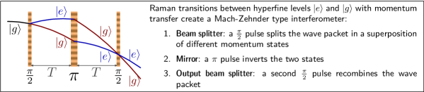
The phase shift at the output of such a light-pulse interferometers arises from three contributions:
-
1.
the difference in the action integral along each path,
-
2.
the difference in the phases imprinted on the atom waves by the beam splitters and mirrors,
-
3.
the term due to the splitting of the wave-packets at the output of the interferometer.
Gravito-inertial effects are found in the first term, but can also be hidden in the second term depending on the chosen reference frame, through movement of the Raman beams. When performing the calculation in an inertial frame, terms 1 and 3 nearly cancel out and leave only the term 2, the laser phase difference between mid-points of classical (non-quantum) trajectories. This shows that interferometric process can be pictured as measuring the position of freely falling atoms on an optical ruler made by the two Raman lasers beating together with a wavevector given by the difference of their wavevectors . This simple picture allows to understand the stringent requirement on the lasers for a high-precision measurement, as their spectral quality determines the quality of the optical ruler.
For a light-pulse interferometer with equal times between the three pulses, in the case of an accelerated frame with no rotation or gravity gradient, the final phase shift is given by
| (1) |
where is the local acceleration: the atom interferometer acts as a gravimeter. Current state-of-the-art atom-gravimeters have a shot-to-shot accuracy of due to technical noise.
1.3 Micro-gravity, the route to enhanced atom-interferometric sensors
Equation 1 shows that the sensitivity of an atom-interferometer increases with interrogation time. The longer the time the atoms spend between the beam splitters, the greater the scaling factor between the accumulated phase shifts and the effect they probe. In order to avoid uncontrolled residual phase-shifts, it is best not to apply fields other than that which is probed during the phase accumulation period. In the case of inertial sensing this implies that atoms must be in free fall between the beam-splitting processes. In Earth-based interferometers, with cold-atom sources, the expansion of the atomic cloud is small, and the interrogation time is limited to a fraction of second by the available fall height, limiting their precision. Atom interferometry in micro-gravity allows for longer free fall and thus increased precision.
2 Atom-interferometric sensors in the Zero-G Airbus
We are conducting atom interferometry experiments for inertial sensing on board an airplane during ballistic flights. Microgravity is obtained via 20 second-long parabolas by steering the plane to cancel drag and follow gravity. Residual acceleration is on the order of . Even though this tropospheric microgravity facility does not provide the environmental quality of a space-borne mission, either on the ISS or on a dedicated platform, it offers the possibility to perform test and qualification campaigns for future space atomic inertial sensor missions. It also provides the required environment for the first comparison of sensors performances and possibly the first fundamental physics test with atomic sensors in microgravity.
2.1 Airborne test of the equivalence principle: an Airbus as an Einstein elevator.
The Einstein equivalence principle states that physics in a freely falling reference frame, in a gravitational field, is locally equivalent to physics without any gravito-inertial fields. An atom interrogated during its free fall in an interferometer on Earth behaves like an atom interrogated in deep-space. But inertial-sensing interferometers have a non-zero physical size and can be subject to tidal effects (e.g. Lense-Thirring). An experiment carried out nearby a massive object is therefore not equivalent to a deep space experiment. On the other hand, there is no difference between an experiment carried in a freely falling airplane and one on a satellite orbiting around the Earth or the Sun.
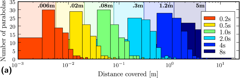
In the airplane, atoms falling in the interferometer’s vacuum chamber experience true free fall as long as they do not hit the chamber walls. The interferometer itself is attached to the airplane and subject to acceleration noise. All movements of the mirrors used for the optical-ruler (the Raman lasers) strongly degrade the performance of the interferometer (see figure 2 (b)). To improve the performance, the interferometer can be left freely flying, released from the airplane, to allow for strong vibration-noise rejection, and increased interrogation time. Since during a few seconds of free fall an object can move by several meters in the airplane (see figure 2 (a)) a rigid construction, called a free flyer, will be required to restrict and damp the displacements of the interferometer. Choosing a free flyer with travel gives a 50% probability of success for a long free fall for each release of the interferometer. As the airplane is rotating about the axis of its wings during the parabola, the rotation of the interferometer cannot be controlled and will give rise to Sagnac shifts. They can be canceled by doing two measurements with the area enclosed by the interferometer reversed.
2.2 Test flight of a prototype micro-gravity interferometer
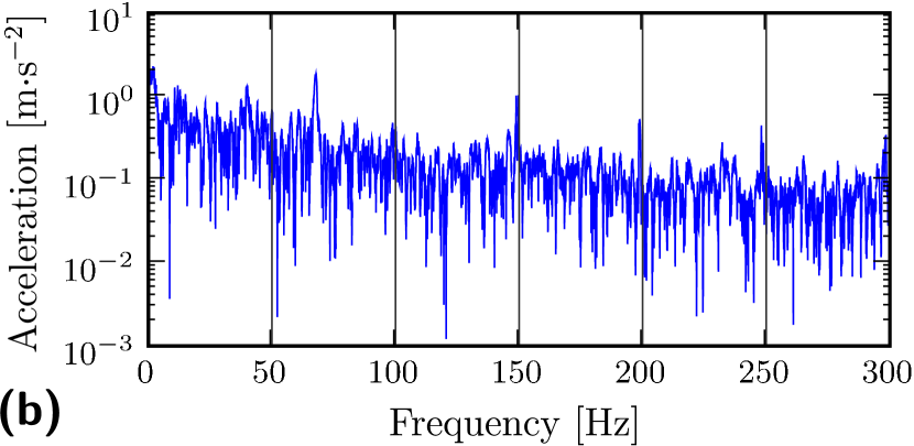
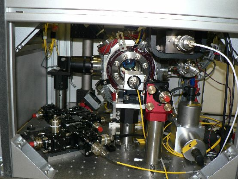
An atom interferometer is made of: a vacuum chambers with optics; lasers sources for cooling and coherent manipulation of atoms; and a stable oscillator (in our case a hyperfrequency source) which serves as a frequency reference for the Raman lasers. A lab experiment weighs at least one tonne and requires a highly-controlled environment. We assembled a prototype atomic source suitable for inertial-sensing in a jet airplane from the I.C.E. collaboration components (see figure 3 (a)). We prepare clouds of cold 87Rb in a Magneto-Optical Trap (MOT) and release them for interrogation during their free fall.
Novel integrated fibered source for rubidium laser-cooling.
Laser cooling and manipulation of atoms requires frequency-stable, narrow-linewidth laser sources. The laser systems generally used in ultracold atom experiments are neither transportable nor reliable and robust enough for our application. Indeed, free-space optical benches with macroscopic cavities often need regular re-alignment. Moving away from the standard semiconductor-laser based design, we have created laser sources at , suitable for atom interferometry with 87Rb, using frequency-doubled fiber lasers and other telecom components at . These novel laser sources have been described in length elsewhere, we will limit ourselves to outlining the successful design choices in light of the test flight.
To achieve a frequency-agile configuration, we use a master laser locked on a rubidium transition and slave lasers which are frequency-locked to the master laser with an arbitrary frequency difference (see figure 4). The master laser (linewidth of ) is a monolithic semiconductor element: a Distributed Feed-Back (DFB) fiber laser, amplified in a Erbium-doped fiber amplifier and frequency doubled in a PPLN waveguide. The resulting light is then sent into a saturated-absorption spectroscopy setup for frequency locking to a rubidium transition. An error signal is obtained by modulating the frequency of the master laser for phase-sensitive detection. Control of the frequency is achieved via a piezoelectric transducer (acting on the DFB laser) but we also change the temperature of the DFB fiber when the piezoelectric voltage approaches its maximum range.
The slave lasers are DFB laser diodes (linewidth of 1.1 MHz). After amplification through an Erbium-doped fiber amplifier they are frequency doubled in free space with two bulk PPLN crystals in cascade (similar to). With a 5W fiber amplifier, we obtain at . The slave lasers are frequency-locked to the master laser by measuring the frequency of a beat-note between the two 1560nm lasers recorded on a fibered fast photodiode. Control of the frequency of the slave lasers is achieved via feedback to their supply current.
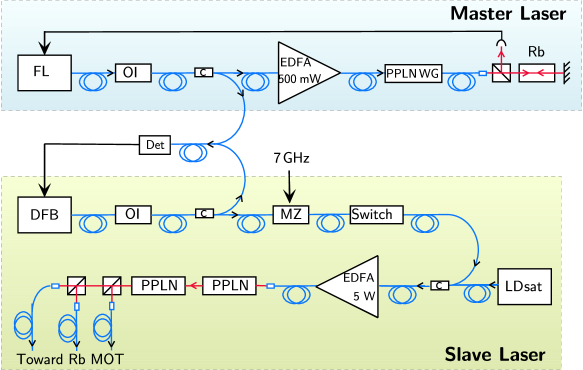
| OI | Optical Isolator |
|---|---|
| FL | Fiber Laser |
| EDFA | Erbium-Doped Fiber Amplifier |
| c | fiber coupler |
| LDsat | saturation Laser Diode |
| MZ | Mach-Zehnder modulator |
| PPLN | Periodically Poled Lithium Niobate |
| PPLN WG | PPLN Wave Guide |
| DFB | Distributed-FeedBack laser diode |
The power of the cooling laser can be adjusted by switching off the input laser of the fibered amplifier with an optical switch after saturating it with a laser source at . The light is not frequency doubled by the PPLN crystals and is filtered by the single-mode fibers. A very good extinction is obtained, limited by the amplified spontaneous emission of the fibered amplifier that is frequency-doubled. Mechanical shutters are used to completely extinguish the lasers over long timescales (they have a dead time), but the use of the saturation diode allows for quicker switching times ().
In order to laser cool 87Rb, an additional frequency (called the repumping laser), located away from the cooling laser, is required. Instead of using another laser, we use a fiber Mach-Zehnder modulator to generate two sidebands apart. One sideband is for repumping and the other is off-resonnace, so causes no ill effects.
Laser light is transported to the vacuum chamber using polarization-maintaining optical fibers. A fiber beam-splitter (Schäfter and Kirchhoff) based on miniature polarizing optics divides the laser-cooling fiber in three to provide separate beams for the operation of the MOT.
The laser sources have proved remarkably robust during the test flight, surviving pressure changes of , temperature changes of , and remaining frequency-locked in spite of the noisy environment. It is worth noting that an amplifier was damaged during flight operations, its output power dropping by a factor of 10. This failure did not prevent the MOT from functioning. The cause is currently being investigated.
A robust transportable interferometer setup.
Keeping with the philosophy of a flexible prototype, the atomic-physics part of the interferometer was built using standard lab equipment mounted on a optics breadboard (see figure 3 (b)). A rigid frame is bolted through the breadboard, holding the vacuum chamber to protect it and meet flight security requirements.
The core of the apparatus is a stainless-steel ultra-high vacuum chamber in which the laser beams intersect for trapping and manipulating the atoms. The chamber has two diameters windows and eight lateral ports. The large number of available ports allows us to dedicate separate windows for different beams and for observation. MOT and compensation coils are directly wound onto the chamber. The rubidium atoms are released from commercially-available alkali-metal dispensers directly into the MOT chamber. While operating the interferometer, the dispensers are run continuously and a dilute () rubidium vapor fills the chamber. There are two pumps: an ion pump and a getter pump, maintaining the required vacuum even during night power cut. No special care has been taken to ensure that all parts of the system are non-magnetic and the ion pump was not shielded. We relied solely on the compensation coils to cancel out the magnetic fields in the surroundings of the atoms.
The six counter-propagating lasers beams of the MOT are made of three retro-reflected beams each expanded out of a fiber by an out-coupler producing a diameter beam. The couplers are positioned on kinematic mounts (New Focus 9071) held by posts bolted on the breadboard. The setup was optimized in our lab in Palaiseau, then carried on a truck away to Bordeaux and loaded into the airplane with no particular precautions. Every day temperature cycled from to . We did not notice any misalignment.
The laser source driving the Raman transition is similar to the cooling laser. The second Raman frequency is achieved as with the repumping frequency by intensity-modulating the laser light. The presence of the second sideband adds new paths to the interferometer, but they need not be taken in account as these secondary interferometers are not closed. For the Raman pulse manipulation, MOT coils are switched from quadrupole configuration to dipole configuration to provide a polarizing field raising the degeneracy between Zeeman sub-levels. The intensity of the lasers can be up to 20 times the saturation intensity of rubidium, which allows for short Raman pulses with weak velocity selection to address broad momentum distributions. The pulse is controlled via an acousto-optical modulator after the frequency-doubling stage. Raman transfer was not tested during this first flight.
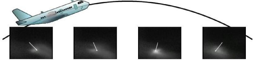
We load atoms of 87Rb in the MOT in one second. A photodiode monitors the fluorescence, which is proportional to the number of atoms. We release the atoms from the MOT and further cool them through a brief phase of optical molasses during which we can prepare the atoms in the lower hyperfine state by turning off the repumping light. The light pulses for the interferometer (see figure 1) can then be applied. The cooling laser is turned back on to detect the atoms still in the MOT volume in a state selective way. The flight of the atoms in the optical molasses was recorded during the test flight. Our preliminary setup had no magnetic shield and the rotation of the Earth’s magnetic field created uncompensated Zeeman shifts. These shifts imbalance the radiation pressure during molasses, limiting the atomic escape velocity (see figure 5).
3 I.C.E.: the next-generation apparatus
Temperatures achieved through laser-cooling techniques reach a limit of around (). Ballistic expansion of laser-cooled atoms thus limits interrogation times to a few seconds . To make full use of micro-gravity (e.g. with a space-borne experiment) further cooling is needed. The limiting factor for atom-interferometric metrology is the size of the atomic cloud after expansion, given by both its initial size and velocity spread. This size is closely related to the phase-space density of the source, which can be seen as an atom-optic equivalent of the luminance of a photonic source. The source of maximum luminance in optics is the laser, and which is widely used in photon-interferometry. In atom-optics such a source is a Bose-Einstein condensate. The intrinsic linewidth of a Bose-Einstein condensate is very narrow, however the momentum-width of a freely falling condensate depends on the trap release process.
Within the I.C.E. project, we are building a next-generation atom interferometer making use of quantum degenerate atomic gases for increased interrogation times during ballistic flights. Degenerate atom sources can be achieved by evaporative cooling, where the depth of a non-dissipative trap is lowered to eject higher energy atoms while relying on two-body collisions to thermalize the cloud, thus lowering its temperature. Magnetic traps, where atoms are trapped near a minimum of magnetic field, are most often used to perform this evaporation. However, releasing atoms from a magnetic trap is an ill-controlled process that will affect the sensor performances. On the contrary, optical-dipole traps, where atoms are trapped near a maximum of laser light intensity, can be controlled with much more precision. Ramping down to zero the power of the trapping laser yields a jerk-free release process. In the I.C.E. interferometer, we transfer the atoms from the MOT to an optical-dipole trap made of two intersecting laser beams at . Efficient capture of the atoms is achieved for a trap depth of a few times their kinetic energy. The phase-space volume of a dipole trap is limited by the available laser power. As a MOT is a rather large cloud, it is best to capture it with the spatially largest possible trap while still deep enough to load the atoms. Using a fiber laser, we can load the atoms using trap diameters up to .
To permit a short duty cycle that allows for high precision measurement and high accuracy, the production of the degenerate atomic source must be fast. For the evaporation process to be efficient, the collision rate needs to increase as the number of trapped atoms decreases. However, lowering the power of the trapping laser reduces the depth of the trap, but not its size, and, as the trap depth goes to zero, so does the density of the trapped atoms and the collision rate. We use a mechanical zoom to change the diameter of the trapping laser beam during the evaporation and optimize the collision rate for quick evaporative cooling.
Bose-Einstein condensates are relatively high-density samples, and the interactions between atoms cannot be neglected. These interactions give rise to uncontrolled shifts in interferometers. Inertial-sensing atom interferometers have a physical extent, and the wave-packets in the different arms of the interferometers spend most of their time non-overlapping. The collisional shifts occur at the beam-splitters, where each atom interacts with the atoms in the other arm . On the contrary, due to Pauli blocking, ultracold, spin-polarized, degenerate fermions do not interact. They suffer no interaction shifts , but, as their phase-space density cannot exceed unity, they form less bright sources and, when released from tight traps, their increased momentum spectrum could limit interrogation times. However, Pauli blocking in Fermi gases and interactions in Bose gases yield similar orders of magnitude for momentum broadening over the range of accessible experimental parameters as long as the interaction is not suppressed via magnetically-tunable Feshbach resonances. Nevertheless, both collisional-shifts and momentum broadening can be strongly reduced by adiabatically opening the trap and reducing the density before the release, or by the use of an external magnetic field to tune the interactions (Feshbach resonances). The I.C.E. interferometer has been designed to operate with fermionic 40K in addition to bosonic 87Rb to allow for comparison of the achievable precisions using different species.
Conclusion
We have successfully tested a cold atom source for inertial sensing in aircraft parabolic flights. With the use of a free-flyer, it will allow interrogation of the freely-falling atoms during several seconds, paving the way for high-precision inertial sensors. The interrogation time is then limited be the residual acceleration. The aircraft is a valid frame for fundamental tests of gravitation theories. Our preliminary results show that laboratory experiments can be adapted for this new experimental platform. Unlike orbital platforms, development cycles on ground-based facilities, either on the plane (it took us 3 months to assemble the test prototype), or on drop towers, can be sufficiently short to allow for the rapid technological evolution for future sensors. Indeed high-precision drag-free space-borne applications require further progress on achieving longer interrogation times using ultra-low velocity atoms. Our new-generation degenerate atomic source design minimizes trap-release and interaction energies for these purposes.
Acknowledgments
The I.C.E. collaboration is funded by the CNES, as are JPB, RAN and NZ’s salaries. Further support comes from the European Union STREP consortium FINAQS. Laboratoire Charles Fabry, ONERA, and LNE-SYRTE are affiliated to IFRAF.
References
References
- [1] A. Peters, K.Y. Chung, S. Chu, Metrologia 38, 25 (2001)
- [2] S. Dimopoulos, et al. Phys. Rev. Lett. 98, 111102 (2007); B. Dubetsky and M. Kasevich, Phys. Rev. A 74, 023615 (2006).
- [3] W.W. Chow, J. Gea–Banacloche, L.M. Pedrotti, V.E. Sanders, W. Schleich, and M.O. Scully. Rev. Mod. Phys., 72, 61 (1985).
- [4] J.F. Clauser. Physica B, 151, 262 (1988); C. Bordé. Phys. Lett. A 140, 10 (1989).
- [5] S.A. Werner, J.-L. Staudenmann, and R. Colella. Phys. Rev. Lett., 42, 1103 (1979).
- [6] R. Colella, A.W. Overhauser, and S.A. Werner. Phys. Rev. Lett. 34, 1472 (1975).
- [7] F. Riehle, Th. Kisters, A. Witte, J. Helmcke and Ch.J. Bordé. Phys. Rev. Lett. 67, 177 (1991).
- [8] M. Kasevich and S. Chu, Appl. Phys., B 54, 321 (1992).
- [9] P.R. Bermann (eds.), Atom Interferometry (Academic, Boston MA, 1997)
- [10] T.L. Gustavson, P. Bouyer, M.A. Kasevich. Phys. Rev. Lett. 78, 2046 (1997).
- [11] T.L. Gustavson, et al. Class. Quantum Grav. 17, 1 (2000).
- [12] B. Canuel, et al., Phys. Rev. Lett. 97, 010402 (2006)
- [13] A. Peters, K.Y. Chung, B. Young, J. Hensley and S. Chu. Phil. Trans. R. Soc. Lond. A 355, 2223 (1997).
- [14] Ph. Laurent, et al. App. Phys. B 84, 683 (2006)
- [15] Study of the Pioneer anomaly: Anderson et al. Phys. Rev. D 65, 082004 (2002)
- [16] C. Lämmerzahl, Appl. Phys. B 84, 551 (2006)
- [17] Gravity Probe B: S. Buchman et al. Advances in Space Research 25, 1177 (2000)
- [18] HYPER Assessment Study Report ESA-SCI(2000)10, European Space Agency (2000)
- [19] Ch. J. Bordé, C. R. Acad. Sci. Paris, t. 2 Série IV, 509 (2001).
- [20] Ch. J. Bordé sl et al., in C. Lämmerzahl, C.W.F. Everitt, F.W. HehlGyros (Eds.), Clocks and Interferometers: Testing Relativistic Gravity in Space, Springer-Verlag (2000)
- [21] D.J. Wineland, et al. Phys. Rev. Lett. 66, 6797 (1992)
- [22] M. Kasevich, S. Chu Phys. Rev. Lett. 67, 181 (1991)
- [23] M.-C. Angonin, P. Tourrenc, P. Delva, Appl. Phys. B 84, 579 (2006)
- [24] R.A. Nyman, et al. App. Phys. B 84, 673 (2006)
- [25] F. Lienhart, et al. App. Phys. B , (2007)
- [26] Y. Lecoq, et al. App. Phys. B 84, 627 (2006)
- [27] R. J. Thompson, et al. Optics Express 11, 1709 (2003)
- [28] T. Kinoshita, T.R. Wenger, D.S. Weiss, Phys. Rev. A 71, 01 162(R) (2005)
- [29] S. Gupta, et al. Science 13, 1723 (2003)
- [30] When suddenly releasing interacting Bose gases from a trap, the release momentum is given by the energy of the bosons in the trap. For trapping frequencies of , the harmonic oscillator length related to the trap is , and the release wave-vector is , with the scattering length of the atoms. For Fermi gases, the spread in wave-vector is given by .
- [31] A. Vogel et al. App. Phys. B 84, 663 (2006)
- [32] http://213.251.135.217/ifraf/