Toward Full Spatio-Temporal Control on the Nanoscale
Abstract
We introduce an approach to implement full coherent control on nanometer length scales. It is based on spatio-temporal modulation of the surface plasmon polariton (SPP) fields at the thick edge of a nanowedge. The SPP wavepackets propagating toward the sharp edge of this nanowedge are compressed and adiabatically concentrated at a nanofocus, forming an ultrashort pulse of local fields. The one-dimensional spatial profile and temporal waveform of this pulse are completely coherently controlled.
pacs:
78.67.-n, 71.45.Gm, 42.65.Re, 73.20.MfTwo novel areas of optics have recently attracted a great deal of attention: nanooptics and ultrafast optics. One of the most rapidly developing directions in ultrafast optics is quantum control, in which coherent superpositions of quantum states are created by excitation radiation to control the quantum dynamics and outcomes Shapiro and Brumer (2006); Rabitz et al. (2000); Apolonski et al. (2004); Zeidler et al. (2005). Of special interest are coherently controlled ultrafast phenomena on the nanoscale where the phase of the excitation waveform along with its polarization provides a functional degree of freedom to control nanoscale distribution of energy Stockman et al. (2002, 2004); Stockman and Hewageegana (2005); Kubo et al. (2005); Sukharev and Seideman (2006); Aeschlimann et al. (2007). Spatiotemporal pulse shaping permits one to generate dynamically predefined waveforms modulated both in frequency and in space to focus ultrafast pulses in the required microscopic spatial and femtosecond temporal domains Wefers and Nelson (1993); Feurer et al. (2003).
In this Letter, we propose and theoretically develop a method of full coherent control on the nanoscale where a spatiotemporally modulated pulse is launched in a graded nanostructured system. Its propagation and adiabatic concentration provide a possibility to focus the optical energy in nanoscale spatial and femtosecond temporal regions. The idea of adiabatic concentration Stockman (2004a, b) (see also Ref. Babajanyan et al., 2000) is based on adiabatic following by the propagating surface plasmon-polariton (SPP) wave of a plasmonic waveguide, where the phase and group velocities decrease toward a limit at which the propagating SPP wave is adiabatically transformed into a standing surface plasmon (SP) mode. This effect has been further developed theoretically Maier et al. (2006); Gramotnev (2005) and observed experimentally. Verhagen et al. (2006)
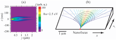
To illustrate the idea of this full coherent control, consider first the adiabatic concentration of a plane SPP wave propagating along a nanowedge of silver Johnson and Christy (1972), as shown in Fig. 1(a); the theory is based on the Wentzel-Kramers-Brillouin (WKB) or quasiclassical approximation, also called the eikonal approximation in optics Landau and Lifshitz (1984) as suggested in Refs. Stockman, 2004a, b. The propagation velocity of the SPP along such a nanowedge is asymptotically proportional to its thickness. Thus when a SPP approaches the sharp edge, it slows down and asymptotically (in the ideal limit of zero thickness at the apex) stops while the local fields are increased and nano-concentrated.
Now consider a family of SPP rays (WKB trajectories) propagating from the thick side of a nanowedge, as shown in Fig. 1(b). One possibility to launch such SPPs is to have nanoscale inhomogeneities (nanoparticles or nanoholes) at the thick edge of the wedge. Each of the optical pulses from the spatiotemporal shaper is focused on the corresponding nanoparticle, scattering from it and generating an SPP wave. This scattering is necessary to impart large transverse momenta on SPPs, which is required for their efficient transverse focusing. These SPP waves propagate toward the sharp edge, adiabatically slow down which increases the field amplitudes, and constructively interfere as they converge at the nanofocus.
The phases of the SPPs rays (i.e., the corresponding wave fronts) are defined by the spatiotemporal modulator in such a way that the rays converge to a reconfigurably chosen point at the sharp edge of the nanowedge where they acquire equal phases. When the SPPs propagate along the rays, adiabatic concentration takes place because the SPP wavelength tends to zero proportionally to the thickness of the wedge. This allows one to focus optical energy at a predefined nanofocus at the sharp edge. The temporal structure of the generated SPPs can be chosen in such a way that at the nanofocus the local fields form an ultrashort pulse. Using spatiotemporal modulation of the excitation field at the thick edge, one can arbitrarily move the nanofocus along the sharp edge. A superposition of such fields can render arbitrary spatiotemporal modulation on the sharp edge, enabling one to exert full control over nanoscale fields in space and time.
Turning to the theory, consider a nanofilm of metal in an plane whose thickness in the direction is adiabatically changing with the coordinate-vector in the plane of the nanofilm. Let be the dielectric permittivity of this metal nanofilm, and be the permittivity of the embedding dielectric. Because of the symmetry of the system, there are odd and even (in the normal electric field) SPPs. It is the odd SPP that is a slow-propagating, controllable mode. The dispersion relation for this mode defining its effective index is
| (1) |
where is the radiation wave vector in vacuum.
Let be a unit tangential vector to the SPP trajectory (ray). It obeys a conventional equation of ray optics Landau and Lifshitz (1984)
| (2) |
where is the length along the ray and .
Now let us consider a nanofilm shaped as a nanowedge as in Fig. 1(b). In such a case, , and these trajectory equations simplify as
| (3) |
From these, it follows that . The SPP wave vector, related to its momentum, is ; this is the conservation of (the transverse momentum). This allows one to obtain a closed solution for the ray. The tangent equation for the ray is , where . From this, we get an explicit SPP trajectory (ray) equation as
| (4) |
where is the focal point where rays with any converge. To find the trajectories, as we use the real part of effective index (1), as WKB suggests.
When the local thickness of the wedge is subwavelength (), the form of these trajectories can be found analytically. Under these conditions, dispersion relation (1) has an asymptotic solution
| (5) |
Substituting this into Eq. (4), we obtain explicit equations of trajectories,
| (6) |
where , and is the slope of the wedge. Thus, each SPP ray is a segment of a circle whose center is at a point given by and . This analytical result is in agreement with Fig. 1 (b). If the nanofocus is at the sharp edge, i.e., , then these circles do not intersect but touch and are tangent to each other at the nanofocus point.
As an example we consider a silver Johnson and Christy (1972) nanowedge illustrated in Fig. 1 (b) whose maximum thickness is nm and whose length (in the direction) is . Trajectories calculated from Eq. (4) for eV are shown by lines (color used only to guide eye); the nanofocus is indicated by a bold red dot. The different trajectories correspond to different values of in the range . In contrast to focusing by a conventional lens, the SPP rays are progressively bent toward the wedge slope direction.
The eikonal is found as an integral along the ray
| (7) |
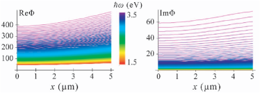
Consider rays emitted from the nanofocus [Fig. 1 (b)]. Computed from this equation for frequencies in the visible range, the phases of the SPPs at the thick edge of the wedge (for ) are shown in Fig. 2 (a) as functions of the coordinate along the thick edge. The colors of the rays correspond to the visual perception of the ray frequencies. The gained phase dramatically increases toward the blue spectral region, exhibiting a strong dispersion. The extinction for most of the frequencies except for the blue edge, displayed in Fig. 2 (b), is not high.
Now consider the evolution of the field intensity along a SPP ray. For certainty, let SPPs propagate along the corresponding rays from the thick edge of the wedge toward the nanofocus as shown in Fig. 1 (b). In the process of such propagation, there will be concentration of the SPP energy in all three directions (3d nanofocusing). This phenomenon differs dramatically from what occurs in conventional photonic ray optics.
To describe this nanofocusing, it is convenient to introduce an orthogonal system of ray coordinates whose unit vectors are (along the ray), (at the surface normal to the ray), and (normal to the surface). The concentration along the ray (in the direction) occurs because the group velocity of SPP asymptotically tends to zero (for the antisymmetric mode) for as where . Stockman (2004a, b) This contributes a factor to the amplitude of an SPP wave.
The compression of a SPP wave in the (vertical) direction is given by a factor of , where is the energy density of the mode. Substituting a standard expression Landau and Lifshitz (1984) for , one obtains explicitly
| (8) |
where and .
To obtain the compression factor for the direction), we consider conservation of energy along the beam of rays corresponding to slightly different values of . Dividing this constant energy flux by the thickness of this beam in the direction, we arrive at
| (9) |
The ray amplitude thus contains the total factor which describes the 3d adiabatic compression: .
Now consider the problem of coherent control. The goal is to excite a spatiotemporal waveform at the thick edge of the wedge in such a way that the propagating SPP rays converge at an arbitrary nanofocus at the sharp edge where an ultrashort pulse is formed. To solve this problem, we use the idea of back-propagation or time-reversal. Lerosey et al. (2007) We generate rays at the nanofocus as an ultrashort pulse containing just several oscillations of the light field. Propagating these rays, we find amplitudes and phases of the fields at the thick edge at each frequency as given by the eikonal . Then we complex conjugate the amplitudes of frequency components, which corresponds to the time reversal. We also multiply these amplitudes by which pre-compensates for the losses. This provides the required phase and amplitude modulation at the thick edge of the wedge.
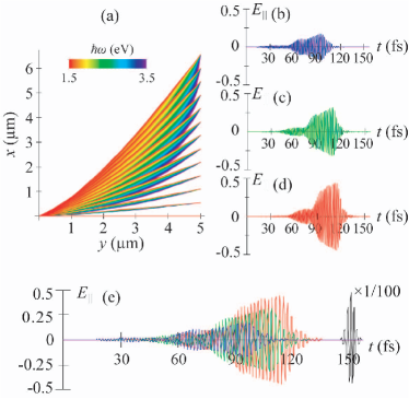
We show an example of such calculations in Fig. 3. Panel (a) displays the trajectories of SPPs calculated according to Eq. (4). The trajectories for different frequencies are displayed by colors corresponding to their visual perception. There is a very significant spectral dispersion: trajectories with higher frequencies are much more curved. The spatial-frequency modulation that we have found succeeds in bringing all these rays (with different frequencies and emitted at different points) to the same nanofocus at the sharp edge.
The required waveforms at different points of the thick edge of the wedge are shown in Fig. 3 (b)-(d) where the corresponding longitudinal electric fields are shown. The waves emitted at large , i.e., at points more distant from the nanofocus, should be emitted significantly earlier to pre-compensate for the longer propagation times. They should also have different amplitudes due to the differences in . Finally, there is clearly a negative chirp (gradual decrease of frequency with time). This is due to the fact that the higher frequency components propagate more slowly and therefore must be emitted earlier to form a coherent ultrashort pulse at the nanofocus.
In Fig. 3 (e) we display together all three of the representative waveforms at the thick edge to demonstrate their relative amplitudes and positions in time. The pulse at the extreme point in (shown by blue) has the longest way to propagate and therefore is the most advanced in time. The pulse in the middle point (shown by green) is intermediate, and the pulse at the center (, shown by red) is last. One can notice also a counterintuitive feature: the waves propagating over longer trajectories are smaller in amplitude though one may expect the opposite to compensate for the larger losses. The explanation of this fact is that the losses are actually insignificant for the frequencies present in these waveforms. What determines the relative magnitudes of these waveforms is the coefficient of the transverse concentration, which is much higher for the peripheral trajectories than for the central ones.
Figure 3 (e) also shows the resulting ultrashort pulse in the nanofocus. This is a transform-limited, Gaussian pulse. The propagation along the rays completely compensates the initial phase and amplitude modulation, exactly as intended. As a result, the corresponding electric field of the waveform is increased by a factor of . Taking the other component of the electric field and the magnetic field into account, the corresponding increase of the energy density is by a factor with respect to that of the SPPs at the thick edge.
Consider the efficiency of the energy transfer to the nanoscale. This is primarily determined by the cross section for scattering of photons into SPPs. For instance, for a metal sphere of radius at the surface of the wedge, one can obtain an estimate , where is the reduced photon wavelength. Setting , we estimate . Assuming optical focusing into a spot of nm radius, this yields the energy efficiency of conversion to the nanoscale of . Taking into account the adiabatic concentration of energy by a factor of , the optical field intensity at the nanofocus is enhanced by one order of magnitude with respect to that of the incoming optical wave.
The criterion of applicability of the WKB approximation is . Substituting and Eq. (5), we obtain a condition . This condition is satisfied everywhere including the nanofocus since and for adiabatic grading. The minimum possible size of the wavepacket at the nanofocus in the direction of propagation, , is limited by the local SPP wavelength: , where is the wedge thickness at the nanofocus. The minimum transverse size (waist) of the SPP beam at the nanofocus can be calculated as the radius of the first Fresnel zone: . Because is constant along a trajectory, one can substitute its value at the thick edge (the launch site), where from Eq. (5) we obtain . This results in ; thus is on order of the maximum thickness of the wedge, which is assumed also to be on the nanoscale.
To briefly conclude, we have proposed and theoretically investigated an approach to full coherent control of spatiotemporal energy localization on the nanoscale. From the thick edge of a plasmonic metal nanowedge, SPPs are launched, whose phases and amplitudes are independently modulated for each constituent frequency of the spectrum and at each spatial point of the excitation. This pre-modulates the departing SPP wave packets in such a way that they reach the required point at the sharp edge of the nanowedge in phase, with equal amplitudes forming a nanofocus where an ultrashort pulse with required temporal shape is generated. This system constitutes a “nanoplasmonic portal” connecting the incident light field, whose features are shaped on the microscale, with the required point or features at the nanoscale.
This work was supported by grants from the Chemical Sciences, Biosciences and Geosciences Division of the Office of Basic Energy Sciences, Office of Science, U.S. Department of Energy, a grant CHE-0507147 from NSF, and a grant from the US-Israel BSF.
References
- Shapiro and Brumer (2006) M. Shapiro and P. Brumer, Physics Reports 425, 195 (2006).
- Rabitz et al. (2000) H. Rabitz, R. de Vivie-Riedle, M. Motzkus, and K. Kompa, Science 288, 824 (2000).
- Apolonski et al. (2004) A. Apolonski, P. Dombi, G. G. Paulus, M. Kakehata, R. Holzwarth, T. Udem, C. Lemell, K. Torizuka, J. Burgdoerfer, T. W. Hansch, et al., Phys. Rev. Lett. 92, 073902 (2004).
- Zeidler et al. (2005) D. Zeidler, A. Staudte, A. B. Bardon, D. M. Villeneuve, R. Dorner, and P. B. Corkum, Phys. Rev. Lett. 95, 203003 (2005).
- Stockman et al. (2002) M. I. Stockman, S. V. Faleev, and D. J. Bergman, Phys. Rev. Lett. 88, 067402 (2002).
- Stockman et al. (2004) M. I. Stockman, D. J. Bergman, and T. Kobayashi, Phys. Rev. B 69, 054202 (2004).
- Stockman and Hewageegana (2005) M. I. Stockman and P. Hewageegana, Nano Lett. 5, 2325 (2005).
- Kubo et al. (2005) A. Kubo, K. Onda, H. Petek, Z. Sun, Y. S. Jung, and H. K. Kim, Nano Lett. 5, 1123 (2005).
- Sukharev and Seideman (2006) M. Sukharev and T. Seideman, Nano Lett. 6, 715 (2006).
- Aeschlimann et al. (2007) M. Aeschlimann, M. Bauer, D. Bayer, T. Brixner, F. J. G. d. Abajo, W. Pfeiffer, M. Rohmer, C. Spindler, and F. Steeb, Nature 446, 301 (2007).
- Wefers and Nelson (1993) M. M. Wefers and K. A. Nelson, Opt. Lett. 18, 2032 (1993).
- Feurer et al. (2003) T. Feurer, J. C. Vaughan, and K. A. Nelson, Science 299, 374 (2003).
- Stockman (2004a) M. I. Stockman, Phys. Rev. Lett. 93, 137404 (2004a).
- Stockman (2004b) M. I. Stockman, in Plasmonics: Metallic Nanostructures and Their Optical Properties II, edited by N. J. Halas and T. R. Huser (SPIE, Denver, Colorado, 2004b), vol. 5512, pp. 38–49.
- Babajanyan et al. (2000) A. J. Babajanyan, N. L. Margaryan, and K. V. Nerkararyan, J. Appl. Phys. 87, 3785 (2000).
- Maier et al. (2006) S. A. Maier, S. R. Andrews, L. Martin-Moreno, and F. J. Garcia-Vidal, Phys. Rev. Lett. 97, 176805 (2006).
- Gramotnev (2005) D. K. Gramotnev, J. Appl. Phys. 98, 104302 (2005).
- Verhagen et al. (2006) E. Verhagen, L. Kuipers, and A. Polman, Nano Lett. (2006).
- Johnson and Christy (1972) P. B. Johnson and R. W. Christy, Phys. Rev. B 6, 4370 (1972).
- Landau and Lifshitz (1984) L. D. Landau and E. M. Lifshitz, Electrodynamics of Continuous Media (Pergamon, Oxford and New York, 1984).
- Lerosey et al. (2007) G. Lerosey, J. de Rosny, A. Tourin, and M. Fink, Science 315, 1120 (2007).