Optical Bistability in Nonlinear Optical Coupler with Negative Index Channel
Abstract
We discuss a novel kind of nonlinear coupler with one channel filled with a negative index material (NIM). The opposite directionality of the phase velocity and the energy flow in the NIM channel facilitates an effective feedback mechanism that leads to optical bistability and gap soliton formation.
pacs:
42.81.Qb, 42.65.Pc, 42.65.TgNonlinear optical couplers have attracted significant attention owing to their strong potential for all-optical processing applications, including switching and power-limiting devices. Transmission properties of a nonlinear coherent directional coupler were originally studied by Jensen 1 , who concluded that a coupler consisting of two channels made of conventional homogeneous nonlinear materials is not bistable.
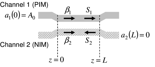
Bi- (or multi-)stability is a phenomenon in which the system exhibits two (or more) steady transmission states for the same input intensity 2 ; 3 . Optical bistability has been predicted and experimentally realized in various settings including a Fabry-Perot resonator filled with a nonlinear material 3 and layered periodic structures 4 . In this Letter we describe a novel nonlinear optical coupler structure that utilizes a negative index metamaterial (NIM) 5 ; 6 in one of the channels and a conventional positive index material (PIM) in another channel as shown in Fig. 1. The linear transmission properties of a similar optical structure were previously studied by Alu and Engheta 7 . We show that such nonlinear coupler (NLC) can be bistable. Bistability occurs owing to the effective feedback mechanism enabled by a fundamental property of NIMs – opposite directionality of the wave vector and the Poynting vector. Moreover, our results suggest that the entirely uniform PIM-NIM coupler structure supports gap solitons – a feature commonly associated with periodic structures 4 , 8 -14 .
Continuous wave propagation in a nonlinear coupler can be described by the following system of equations:
| (1) | |||||
| (2) |
where and are the complex amplitudes of the modes in the PIM and NIM channels respectively, and are the coupling coefficients defined as in Ref. 1 , is the mismatch between the propagation constants in the individual channels, , (), is the sign of the refractive index , and are linear frequency-dependent dielectric permittivity and magnetic permeability, is carrier frequency, is the nonlinear (electric) susceptibility, and is the speed of light in a vacuum. In the case of PIM-NIM coupler is positive, while is negative.
Assuming the form for the solutions of Eqs. (1, 2) in the linear regime, we find the following relation between and for the PIM-NIM coupler
| (3) |
which indicates the presence of a bandgap for . The photonic bandgap is usually a feature typical for periodic or distributed feedback (DFB) structures such as fiber Bragg gratings (FBGs) or thin film stacks 7 . Formation of the bandgap in a uniform structure considered here is one of the unique properties of the PIM-NIM coupler arising from introduction of the NIM into the nonlinear coupler. Introducing two parameters and , the nonlinear counterpart of the relation 3 can be written in the form
| (4) | |||||
| (5) |
where
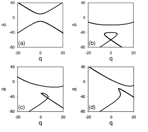
is the nonlinearity coefficient. Figure 2 shows linear (a) and nonlinear curves (b)-(d) for the case of self-focusing Kerr nonlinearity. In Fig. 2(b) both PIM and NIM channels are nonlinear, with the same nonlinearity coefficients. Beyond a critical power level, the lower branch of the curve forms a loop. Both linear and nonlinear curves in Fig. 2(a) and 2(b) resemble dispersion relations found in the case of linear and nonlinear FBG 8 ; 15 , with the difference that in the nonlinear case the effect of cross-phase modulation has been neglected and forward and backward waves are spatially separated. However, importantly, in the case of PIM-NIM NLC both channels are made of homogeneous material with no periodicity or an external feedback mechanism (such as a cavity). However, the effective feedback mechanism is provided by the inherent property of the NIMs, that is opposite directionality of the phase and energy velocities. As shown in Fig. 1, while the propagation vectors of the waves propagating in both NLC channels point in the same direction assuring a necessary phase-matching condition, the Poynting vectors corresponding to the energy flow direction point in opposite directions. As light propagates in the PIM channel in the forward direction it continuously couples to the NIM channel where it flows in the backward direction. Therefore, the PIM-NIM coupler acts as an effective DFB structure. Figure 2(c) corresponds to the case of different nonlinear coefficients in the two channels, while Fig. 2(d) corresponds to the case of the nonlinear PIM and linear NIM channel. Figures 2(c) and 2(d) also illustrate that there are more degrees of design freedom in the NLC case in comparison with the DFB structures since in general case the nonlinear coefficients and as well as the coupling coefficients and may be not identical and can be properly designed.
Although in general case and , in order to illustrate basic new physical effects associated with the PIM-NIM NLC, in the following discussion we assume identical linear coupling coefficients and nonlinear coefficients . Then, making the substitution and , where , , and are real functions of , the equations for and can be written in the form
| (6) | |||||
From the system of equations (6) the constants of the motion are given by
| (7) | |||||
| (8) |
where and . is defined by the boundary conditions at and , where is the length of the coupler. The expressions (7) should be compared to that of conventional PIM-PIM NLC, in which case .
Then, power evolution in channel 1 is described by the equation
| (9) |
If light initially is launched into channel 1, i.e. , , then . In the case of and Eq. (9) reduces to
| (10) |
Introducing new variable and , where , Eq. (10) can be written in the form
| (11) |
where . The solution of Eq. (11) is given by
| (12) |
where as follows from the boundary condition, sn is the Jacobi elliptic function 16 . Using the properties of Jacobi elliptic functions and Eq. (12) the solutions for and can be written in the form
| (13) | |||||
| (14) |
where
The parameter can be found using the transcendental equation
| (15) |
Finally, one can define transmission and “reflection” coefficients for the nonlinear coupler as
| (16) | |||||
| (17) |
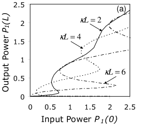
Figure 3(a) shows output power as a function of input power for three values of (solid line), (dot-dashed line), and (dashed line), assuming is varying, the coupler length (in the units of length) is fixed and . As the coupling between the channels increases and the effective feedback mechanism establishes, PIM-NIM NLC becomes bistable or more generally multistable such as in the case of . Its transmission characteristics are very similar to those of the DFB structures 8 -11 with an important fundamental difference that bistability in the PIM-NIM coupler is facilitated by the effective feedback mechanism originating from the NIM’s intrinsic property. Figure 3(b) shows the transmission coefficient as a function of input power for two values of (solid line) and (dashed line), assuming is varying, the coupler length is fixed and . As the nonlinearity coefficient decreases the threshold of bistability shifts to the higher values as expected.
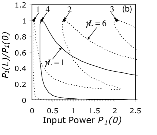
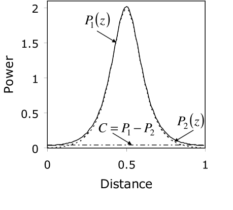
The phenomenon of bistability in DFBs is closely related with the notion of gap solitons 7 -15 . As shown in Fig. 3(b), the transmission coefficient approaches at the points 1, 2, 3 and 4, suggesting the existence of transmission resonances. At the resonance, corresponding to a point 1 in Fig. 3(b), spatial power distributions (solid line) and (dashed line) peak in the middle of the structure as shown in Fig. 4. The dot-dashed line in Fig. 4 shows the constant of the motion . At this transmission resonance incident light is coupled to a soliton-like static entity that peaks in the middle of the structure and is known as a gap soliton 10 ; 11 . Nonstationary gap solitons in PIM-NIM NLC analogous to those found by Aceves and Wabnitz 13 in a context of periodic media will be discussed elsewhere. It is notable that a gap soliton, usually existing in periodic structures, forms in a uniform structure in the case of the PIM-NIM coupler, owing to the new backward-coupling mechanism in the PIM-NIM coupler.
In summary, we found that backward coupling between the modes propagating in the PIM and NIM channels enabled by the basic property of NIMs, oppositely directed phase and energy velocities, results in optical bistability in PIM-NIM NLC and gap soliton formation. These effects have no analogies in conventional PIM-PIM couplers composed of uniform (homogeneous) waveguides with no feedback mechanism.
This work was supported in part by the ARO Award # 52730-PH, ARO-MURI Award # 50342-PH-MUR, by the NSF Award # DMS-050989, by State of Arizona grant TRIF (Proposition 301) and by the RFBR Award # 06-02-16406
References
- (1) S. M. Jensen, IEEE J. Quantum Electron. QE-18, 1580 (1982).
- (2) C. Bowden, M. M. Ciftan, and H. Robl, Eds. Optical Bistability, (Plenum, New York, 1981).
- (3) H. M. Gibbs, Optical Bistability, (Academic Press, Orlando, FL, 1985).
- (4) H. G. Winful, J. H. Marburger, and E. Garmire, Appl. Phys. Lett. 35, 379 (1979).
- (5) V. G. Veselago, Soviet Physics Uspekhi, 10, 509 (1968).
- (6) V. M. Shalaev, V. M., Optical Negative-Index Metamaterials, Nature Photonics 1, 41 (2007).
- (7) A. Alu and N. Engheta, in Negative-Refraction Metamaterials ed. G. V. Eleftheriades and K. G. Balmain (Wiley, New York, 2005).
- (8) C.M. de Sterke and J.E. Sipe, in Progress in Optics, edited by E. Wolf (North-Holland, Amsterdam, 1994), Vol. XXXIII, pp. 203–260
- (9) H. G. Winful, Ph.D. Dissertation, University of Southern California, 1981.
- (10) W. Chen and D. L. Mills, Phys. Rev. Lett. 58, 160 (1987).
- (11) D. L. Mills and S. E. Trullinger, Phys. Rev. B 36, 6269 (1987).
- (12) D. N. Christodoulides and R. I. Joseph, Phys. Rev. Lett. 62, 1746 (1989).
- (13) A. B. Aceves and S. Wabnitz, Phys. Lett. A 141, 37 (1989).
- (14) B. J. Eggleton, R. E. Slusher, C. M. de Sterke, P. A. Krug, and J. E. Sipe, Phys. Rev. Lett. 76, 1627 (1996).
- (15) G. P. Agrawal, Applications of Nonlinear Fiber Optics (Academic Press, San Diego, 2001).
- (16) M. Abramowitz and I. A. Stegun (Eds.), Handbook of Mathematical Functions with Formulas, Graphs, and Mathematical Tables, (9th printing. New York: Dover, 1972).