Characteristics of phonon transmission across epitaxial interfaces: a lattice dynamic study
Abstract
Phonon transmission across epitaxial interfaces is studied within the lattice dynamic approach. The transmission shows weak dependence on frequency for the lattice wave with a fixed angle of incidence. The dependence on azimuth angle is found to be related to the symmetry of the boundary interface. The transmission varies smoothly with the change of the incident angle. A critical angle of incidence exists when the phonon is incident from the side with large group velocities to the side with low ones. No significant mode conversion is observed among different acoustic wave branches at the interface, except when the incident angle is near the critical value. Our theoretical result of the Kapitza conductance across the Si-Ge (100) interface at temperature K is . A scaling law at low temperature is also reported. Based on the features of transmission obtained within lattice dynamic approach, we propose a simplified formula for thermal conductance across the epitaxial interface. A reasonable consistency is found between the calculated values and the experimentally measured ones.
pacs:
66.70.+f, 44.10.+iI Introduction
The interfacial thermal conductance plays a critical role in nanometer-scaled devicesdgcahill ; ETswartz . Kapitza resistance Kapitza was first discovered in 1940s. Although much work, both theoretical and experimental, dgcahill ; ETswartz ; Kapitza ; walittle ; G-Chen ; experimental ; dayang ; zhao ; wang has been done since then, the characteristic behavior of phonon transmission across the interface is still not clear. The continuum elastic wave model walittle may be inaccurate when the details of atomistic structures and phonon dispersions are considered. The diffusive scattering theoryETswartz neglects the wave property of phonons. Here we study phonon transmission across interfaces with the lattice dynamic approachdayang ; wang , which can simulate the phonon transmission across interfaces atomistically from the first-principles. We concentrate on the phonon transmission at a single epitaxial interface to capture salient features of transmission.
The paper is organized as follows. We first present the method employed in this study. Using this method we calculate the dependence of phonon transmission on frequency, the azimuth angle, the incident angle, the mode conversion at the Si-Ge interface and at the Si-GaP interface in Section II. Some features of phonon transmission are obtained and discussed. Finally, on the basis of these features, we propose a simplified formula for thermal conductance across interface. A comparison between the calculated thermal conductance and the experimentally measured values is made.
II Method
We consider the problem of phonon transmission across an epitaxial interface. Two types of important crystal structures in semiconductors, diamond and zinc-blend, are chosen in this study. The crystals on each side of the interface are assumed semi-infinitedayang ; wang ; zhao . For simplicity, we also neglect the defects possibly existing between the two crystal solids and assume that the interface is an ideal epitaxial interface. Lattice dynamic approach also requires that the harmonic approximation for solids is valid. This condition is usually satisfied at low temperatures. For the scattering of waves at interface, we remark that the nonlinear nonlinear effect may be less important than the elastic scattering at low temperature because the thickness of boundary area at the interface is smaller than the mean free path of phonons.
We follow the scattering boundary method in Ref. dayang, ; wang, . We write the solutions on the incident side and on the transmitted side with the unknown component coefficients expressed as follows. If a normal mode is incident from the left lead, the scattering solution for the perfect leads can be assumed as
| (1a) | |||||
| (1b) | |||||
where denote the th atom in the unit cell, and and refer to the different polarized branches of incident, reflected and transmitted waves. Frequency is denoted as . Wavevectors for the incident, reflected, and transmitted waves are and , respectively. The superscript and indicate the left and the right. In these equations, , are the amplitude transmission/reflection coefficients from mode on the lead to mode on lead , and to mode on lead . The wave vectors and satisfy . Note that frequency does not change because the system is linear.
In this paper, we consider the phonon transmission across two types of epitaxial interfaces: the interface between silicon and germanium and the interface between silicon and gallium phosphide. Now the problem is to determine the wave numbers for the possible branches of the reflected and the transmitted waves. Since the system is homogeneous in the and directions, the transverse components of the wave vector for the reflected waves and for the transmitted waves have the same values as that of the incident wave , that is ; . The longitudinal components, and , satisfy . We solve the nonlinear equation to find or for the interface with the numerical method in Ref. numericalrecipes, . For the interface, we utilize a more efficient eigenvalue method to obtain the solutions of nonlinear equations.zhao The wave vectors and are identified from these solutions to satisfy the following conditions: (i) The reflected waves should have the negative group velocity so that the phonon energy of the reflected waves will propagate back to the direction. (ii) The transmitted wave should have the positive group velocity so the phonon energy of the transmitted waves will propagate to the direction. (iii)When the wave numbers for the reflected and transmitted waves are complex, they are identified from the solutions to satisfy and so that these waves decay in space. Actually these decay waves with complex wave number do not propagate any energy and the phase difference along direction for atoms in the neighboring unit cells is . But they are physically possible modes at the interface and must be considered in the scattering boundary method.
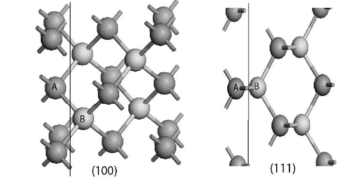
Now we consider the dynamic equations for atoms at the interface. The and interface between the diamond structure or the zinc-blend structure is illustrated in Fig. 1. We assume that the transverse directions at the interface are infinitely large so that the boundary atoms on each side, e.g., atoms in the figure, are translational invariant. The dynamic equations for position atoms are equivalent, and similarly for position atoms on the other side of the interface. So we only need to consider the dynamic equations for atom and for atom at the interface. Under the harmonic approximation, these dynamic equations at a given frequency can be written as where denotes the atomic mass for each atom, is the oscillation amplitude and is the force constants. The force constants across the interface are chosen as the symmetrized . After substituting Eq.(1) into this dynamic equation, we get six equations with six unknown coefficients. This system of equations can be solved by a conventional method. The energy transmission from mode to mode is given by
| (2) |
Here is the reduced group velocity wang along direction for mode in the left lead, defined by where is the group velocity and is the lattice constant for the left. Similar meaning holds for . The total reflection and transmission coefficients for are given, respectively, by
| (3a) | |||||
| (3b) | |||||
The group velocity along direction is calculated through the dynamic matrix as
| (4) |
where is the dynamic matrix and the eigenvector of the dynamic matrixwang . Note that the energy conservation relation, Eq.(3b), is satisfied automatically. This can be used as a check. With the relation Eq. (3), we can get the Kapitza conductance as
| (5) |
where is the transmission wang calculated from Eq. (3), is the volume and is the Bose-Einstein distribution for the branch mode. When using Eq. (5), we compute Kapitza conductance from the Si side. The lattice constants for Si conventional unit cell is Å.
III Models and Numerical Results
In this section, we report the dependence of phonon transmission on frequency, the azimuth angle, and the incident angle across the Si and Ge interface. We then consider the mode conversion problem at interface. Phonon transmission across a kind of zinc-blend interface: Si-GaP is also studied to investigate the lattice structure effect on transmission.
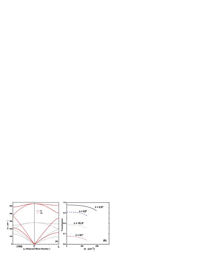
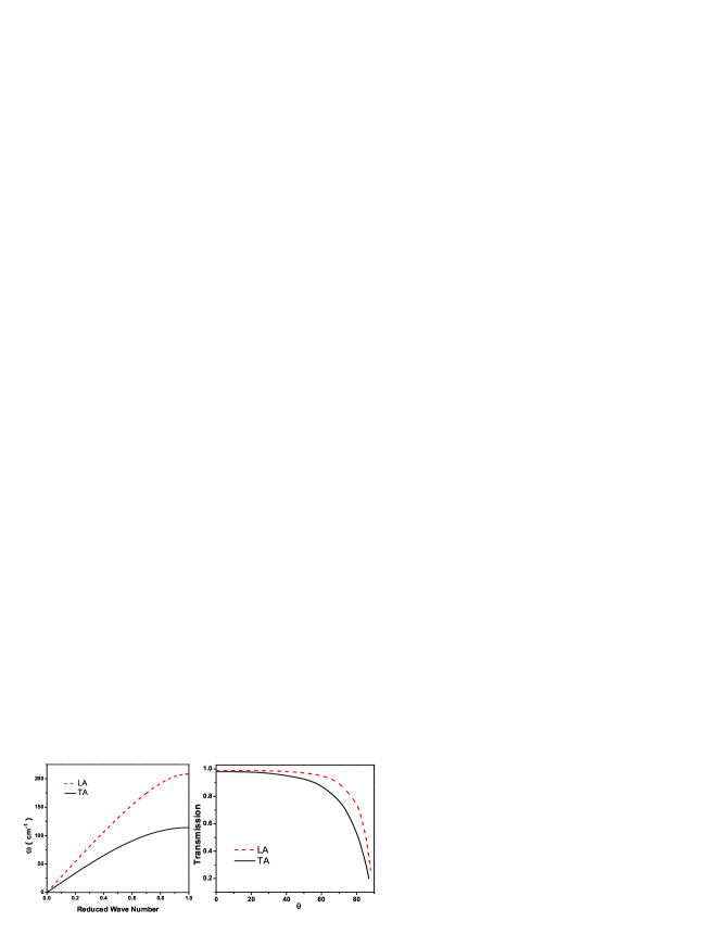
The atomic masses for Si and Ge are and , respectively. After optimizing the structure using Tersoff potential dwbrenner , we obtain the linearized force constants under small displacement. Due to Tersoff potential truncation function,dwbrenner only four nearest atoms need to be considered for each atom. The phonon dispersions for the Si and Ge along the direction can be calculated through the linearized force constants from the dynamic matrix and are illustrated in Fig. 2. The maximum frequency of LA branch along for Si and Ge are and , respectively. Compared with the experimental Si and Ge phonon dispersions giannozzi , there is a discrepancy between the calculated phonon frequency in Fig. 2 and the experimental values. This inaccuracy comes from the lack of more neighboring atoms for Tersoff potential, apart from the first neighboring ones. The ab initio methodabinit which can include higher order neighboring atoms is desirable for the more elaborate phonon dispersion relations. However, we find that the inclusion of higher order neighboring atoms will make the calculation of energy transmission very difficult because the solutions of or at a given frequency is rather complicated. We estimate that such errors of phonon dispersion relation in the Briullouin boundary will not have much influence on the energy transmission across the interface. The force constants from the first neighboring atoms play a main role in the computation of phonon dispersion relations. The cut-off frequency of energy transmission across the interface will not approach closely to the boundaries of the Briullouin boundary apart from a few high symmetry directions. The transmission decreases very rapidly when the frequency is near cut-off, which can be seen from Fig.2(B). Therefore, we think that the inaccuracy of the Briullouin boundary values from Tersoff potential will not significantly change the results of energy transmission across the interface.
III.1 Dependence on angular frequency
The transmission’s dependence on angular frequency across a Si-Ge interface is shown in Fig. 2(B). The incident acoustic wave is longitudinally polarized with an incident angle in plane. For waves with the incident angle below about , the transmission falls into a very narrow range approximately from to and decreases slightly with the increase of frequency before it reaches its cut-off frequency. Here the cut-off frequency means that beyond this point the phonon transmission equals zero. There is an abrupt decrease in phonon transmission when the frequency is near this value. When the incident wave is normal to the interface along direction from Si to Ge, the transmitted waves are also along direction. Thus, the cut-off frequency of transmission can be easily determined from the phonon dispersion of Ge. This can be shown from Fig. 2(B). The cut-off frequency is about for the wave with the incident angle , while the endpoint frequency of the longitudinal acoustic wave branch for Ge along direction is , which agrees with the cut-off frequency of transmission for the normal incident wave. In Fig. 2(B), for clarity, we only plot the transmission before its abrupt jump to zero. For transversely polarized incident acoustic waves, we also have observed a similar phenomenon. It can be concluded that the acoustic phonon transmission from Si to Ge varies in a narrow range with the increase of frequency, independent of the the property of its polarization. Note that the phonon wave is incident from the material (Si) with a larger group velocity to the material (Ge) with a smaller group velocity. This conclusion also holds in our calculations of the transmissions for other incident acoustic waves, not only in plane, but also with azimuth angle . We remark that this small change of phonon transmission with the frequency for incident wave at the incident angle can be neglected for a approximate estimation of thermal conductance across an interface.
III.2 Spatial angular dependence
III.2.1 Azimuth angle and symmetry of the interface
We find that the phonon transmission’s dependence on the azimuth angle of the incident wave is related to the symmetry of the interface. The results of the transmissions for the longitudinal acoustic waves incident from Si to Ge are shown in Fig. 3. It can be seen from Fig. 3 that the phonon transmission shows little dependence on the azimuth angle at incident angle both for the and interface. However, when the incident angle increases beyond , there are peaks in transmission with the variation of the azimuth angle. The peaks reveal the anisotropy of the interface. There is a four-fold symmetry axis in the direction in Si or Ge and a three-fold symmetry axis along the direction. These symmetries have evidently been shown in the phonon transmission across the related interface. In Fig. 3, there are four-fold symmetrical peaks separated by in the transmission across the interface. Three three-fold symmetrical peaks separated by appear in the transmission across the interface.

III.2.2 Critical incident angle
We next report the result of the dependence of energy transmission on the incident angle. A continuum wave incident on a surface with an incident angle is refracted in accordance with Snell’s law. It would be an interesting question if there is a critical angle for discrete lattice waves. We calculated the phonon transmission incident from Si to Ge and incident from Ge to Si. The dependence of transmission on the incident angle are illustrated in Fig. 4 for the Si-Ge interface.
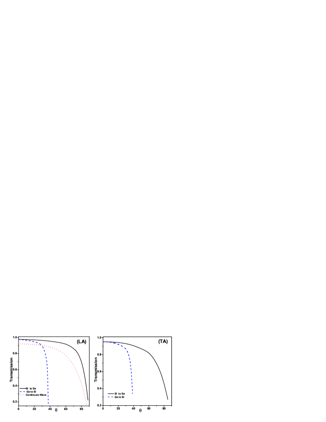
It can be seen from Fig. 4 that when the angle for the phonon incident from Si to Ge increases, energy transmission decreases slowly. The incident angle from Si to Ge can be extended to as large as . In contrast to the transmission from Si to Ge, for waves incident from Ge to Si, there exists a critical angle, about for and for , above which the transmission is very small. We can estimate the critical angle with the help of Snell’s law for continuum wave. The group velocities calculated from the dynamic matrix in this paper for longitudinally polarized waves along the direction are Km/s and Km/s, repectively. The Snell’s law of continuum wave model gives the critical angle from Ge to Si. This value is a little lower than the observed critical angle value. However, we can still think that the Snell’s law holds approximately.
When the incident waves from Si to Ge and from Ge to Si are both normal to the surface (), the transmissions from both sides are for waves and for waves. We use the acoustic mismatch model walittle to estimate , where and denote the acoustic impedance defined as . Here is the mass density and is the group velocity. Here we take and . The values of group velocities for waves are stated in the previous paragraph. It can be seen that the acoustic mismatch model in Ref walittle, well describes the transmission for normal incident waves.
To investigate the difference in the transmission on the incident angle between the lattice dynamic approach and the continuum wave model, we also calculated the energy transmission of the continuum wave. auld The results for Si-Ge interface is illustrated in Fig. 4. The procedure of calculation is as follows. First, the amplitudes transmission auld is computed from the Fresnel equation , where and is the wave impedance for the incident and refraction crystal. Here the mass density and take the value in the preceding graph. The stiffness constants are , respectively. The angle of incidence and the angle of transmission satisfy the Snell’s Law. The energy transmission for the continuum wave is calculated through the formula , where , are the group velocities for the incident and refraction continuum waves. It can be seen that the isotropic continuum wave gives a similar dependence of transmission of the incident angle. The result for the continuum wave is close to the result of lattices wave.
III.3 Mode conversion at the interface
The mode conversion at the interface would be an interesting problem to pursue. There are two types of mode conversion for thermal transmission across the boundary: acoustic-optical (AO) and acoustic-acoustic (AA). We neglect the optical-optical conversion because the corresponding frequencies do not overlap in our model. We think that this optical-optical conversion’s contribution to thermal transport is trivial because of its relatively low group velocity and high energy.
AO conversion. We did not observe significant AO conversion in our simulation of phonon transmission at the Si-Ge interface. The AO conversions in our results are very small, no more than and fall in a very narrow frequency range. This result is different from the reported results in Ref. zhao, . We think this maybe come from the empirical potential chosen in our paper, which results in different group velocities. To estimate the maximum ratio of a possible acoustic-optical mode conversion, A simplified 1D toy chain model wang can be composed because it can be assumed that the AO conversion will be easier for both longitudinal waves in one dimension. However, the results in Ref. wang, find that the energy transmission contributed by the AO conversion is trivial in comparison with the acoustic-acoustic transmission. This is due to the large mismatch in their group velocities.
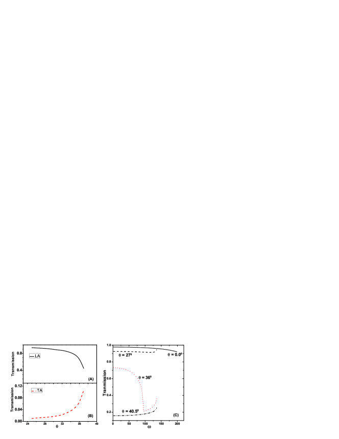
AA conversion. Apart from the possible AO conversion, there are several different polarized acoustic branches. Can the the conversion among these different acoustic branches occur at the interface? Our simulation did not find significant conversion among these different polarized branches, except when the angle of incidence is near the critical angle. The reflected and transmitted waves are both LA waves when the wave incident is longitudinally polarized. The same is true for the TA wave. The AA conversion among different polarized acoustic branches only takes place when the angle of incident is close to the critical angle for wave incident from Ge to Si. Fig. 5 shows the transmission of the longitudinally polarized wave incident from Ge to Si. The mode conversion of is shown in pictures (A) and (B) in Fig. 5. It can seen that the ratio converted from LA to LA decreases with the increase of the angle of incident. The ratio converted from LA to TA increases rapidly to about near the critical angle. This behavior of mode conversion taking place near the critical angle maybe result from the suppression of transmission due to the Snell law. We also find that the presence of the possible reflected waves influence the transmission. For example, in contrast to the transmission from Si to Ge, the dependence of mode wave transmission on frequency from Ge to Si shows a rich character as illustrated in Fig. 5. For wave with the incident angle , the transmission first decreases with the increase of frequency. But when the frequency goes over a certain value, for example for , the transmission begins to increase. This behavior can be understood by the mode conversion at the interface. It can be seen from Fig. 2 that the maximum frequency for modes in Ge is about . When the frequency is below this value, there are modes for the reflected wave; but over this value, the reflected wave cannot be converted into modes. The transmission increases due to lack of reflected modes, .
III.4 Transmission across the interface between diamond and zinc-blend structure
During the calculation of the transmission of Si-Ge interface, the atomic masses are uniformly distributed both for Si and Ge on each side. There is another important type of lattice structure in the semiconductor materials. That is the zinc-blend structure, where the atomic masses in the sublattice are different.
Here we consider an example of gallium phosphide(GaP). To simplify the problem, we only consider the valence-force and neglect the Coulomb interaction between the charges when computing the phonon dispersion of GaP. This is a valid approximation when we consider the acoustic phonons that play major role in the phonon transmission across the interface. The calculated acoustic phonon dispersion curves along for Gap is plotted in Fig. 6. The endpoint values of frequencies along for and are about and , respectively. It can be seen that valence-force constants approximately describe the acoustic branches gap of GaP. The results of phonon transmission for and modes across a Si-GaP interface are illustrated in Fig. 6. We find a consistent dependence on frequency, spatial angular and a similar phenomena of mode conversion with that of Si-Ge interface. The dependence of transmission on the angle of incidence is illustrated in Fig. 6.
III.5 Temperature dependence of Kapitza conductance
The Kapitza conductance with the change of temperature is calculated using Eq. (5), and are illustrated in Fig. 7(A).
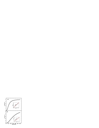
The Kapitza conductance for Si-Ge interface calculated from our model is when K. When the temperature goes beyond K, we find that the Kapitza conductance changes little with the temperature and is saturated. For comparison, we plotted the heat capacity of Si in Fig. 7(B). It can be seen that the heat capacity continues to increase with the temperature when K. In comparison with the heat capacity, the saturation of Kapitza conductance can be accounted by negligible contribution of energy transmission from high frequency at low temperatures, as illustrated in inset of Fig. 7. The Kapitza conductance scales as , while the heat capacity scales as in accordance with the Debye model. We have sampled enough points in the first Brillouin zone to ensure that Kapitza conductance and heat capacity converge numerically. However, due to the small deviation from the value of three, we cannot rule out the possibility that the exponent for Kapitza conduction is also 3. Ref. dayang, reported Kapitza conductance scaled at low temperature for interface irrespective of the properties for the left and right lead. The temperature dependence of Kapitza conductance is an intriguing problem ETswartz , though much experimental work has been done on this field. Most experiments gave for solid interface as reviewed in Ref. ETswartz, . So far no experiment result is available for the temperature dependence for the Si-Ge interface. Compared with the results of Ref. dayang, our discrepancy from comes from the anisotropy of the energy transmission because of the diamond structure used for calculation of the transmission, while Ref. dayang, took an isotropic assumption for their calculation.
IV A new simplified approximate formula
To get a simplified expression, we make the follow approximation on the basis of the features of transmission discussed above. (1) For transmission with a given incident angle , we assume that it is independent of the frequency. (2) We neglect the dependence on the azimuth angle. (3) The conductance can be calculated from either the left or the right side.wang They give the same result across the interface. It is found that the transmission from the high group velocity to the low velocity side has a simpler feature. We calculate the transmission from the high to the low velocity side. The dependence of transmission on the incident angle for a polarized waves is formulate as . Here is the transmission at with the angle of incident , and is given by
| (6a) | |||||
| (6b) | |||||
Here is the acoustic impedance for the polarized wave and is the lattice constant. We have incorporated the effect of difference in lattice constants of the crystal. It can be seen from Fig. 4 that the cosine function is a valid approximation. (4) Mode conversion at the interface can be neglected. (5) Since thermal conductance is contributed mainly by acoustic waves, we can assume that the upper limit of frequency of acoustic waves is characterized by the Debye temperature of the side with the group velocity. A linear dependence of phonon dispersion relation is used because thermal conductance is mainly due to acoustic waves. The group velocity along in Eq. 5 is given by . Under these conditions, we have a simplified thermal conductance (Kapitza conductance) as
| (7) |
Here is the group velocity of the incident side with the large group velocity. The upper limit is given as , where is the Debye temperature for the other side with low group velocity.
| (Å) | (K) | |||||
|---|---|---|---|---|---|---|
| Si | 2.329 | 5.43 | 8.43 | 5.84 | 1.63 | 640 |
| Al | 2.699 | 4.05 | 6.24 | 3.04 | 2.42 | 394 |
| 3.97 | 4.76 | 10.89 | 6.45 | 2.656 | 1024 | |
| Bi | 9.79 | 4.75 | 1.972 | 1.074 | 1.194 | 120 |
| Pb | 11.598 | 4.95 | 2.35 | 0.97 | 1.463 | 105 |
| Diamond | 3.515 | 3.57 | 17.52 | 12.82 | 1.8278 | 1860 |
We use Eq. (7) to calculate a few interfaces across which the experimentally measured thermal conductance is available. The parameters taken are shown in Table 1. The results of calculation are shown in Fig. 8.
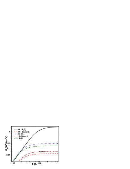
We list the experimental values and our calculated values in Table 2.
| Al/ | Pb/Diamond | Bi/Diamond | Pb/Si | Bi/Si | |
|---|---|---|---|---|---|
| Exp. Values | 1.2 | 0.125 | 0.06 | 0.13 | 0.1025 |
| Cal. Values | 2.5 | 0.013 | 0.02 | 0.10 | 0.0640 |
It can be seen that the calculated values are consistent with the experimental values except for the interface Pb/Diamond. The large deviation for Pb/Diamond interface between the calculated and experimental values maybe come from the nonlinear scattering effect at the interface. It cannot be explained in the reach of the method employed in this paper.
V discussion and Conclusion
We have studied the features of phonon transmission across the epitaxial interfaces by lattice dynamic approach. The transmission is found to change slightly with the frequency for polarized waves with a given incident angle from the high group velocity side to the low group velocity side. The dependence of transmission on the azimuth angle is related to the symmetrical properties of the interface for waves with larger angle of incident. A critical angle exists for transmissions from the low group velocity side to the higher group velocity side. Dependence of transmission on the mode conversion at the interface is trivial except when the incident angle is close to the critical angle. Thermal conductance across the epitaxial interfaces is dominantly contributed by the acoustic waves and is insensitive to the mass distribution of different lattice positions. Kapitza conductance across the Si-Ge(100) interface shows a dependence on temperature, which is very close to behavior. A simplified formula for the estimation of thermal conductance across the interface is proposed in the light of features found by lattice dynamic approach. We remark that this formula can give a valid estimation of Kapitza conductance across solid epitaxial interfaces when nonlinear phonon scattering is unimportant. We think nonlinear scattering sometime maybe important for the interfaces between materials with the higher Debye temperature and the lower Debye temperature, such as Pb-diamond. Such a nonlinear effect cannot be captured in the current lattice dynamic approach. From the calculation, the nonlinear effect maybe contribute to the increase of thermal conductance across the solid interface by breaking the selecting rules between the linear phonon dispersion relations. The phase relations among the incident wave and the reflected, transmitted waves have not been considered because they will not influence the energy transmission across the interface. A possible existence of lattice dislocation or disorder is not included in the present lattice dynamic approach.
ACKNOWLEDGEMENTS
We think Dr. Jingtao Lü for careful reading of the manuscript. This work is supported in part by a Faculty Research Grant of National University of Singapore.
References
- (1) D. G. Cahill et al., J. Appl. Phys. 93, 793 (2003).
- (2) E. T. Swartz and R. O. Pohl, Rev. Mod. Phys. 61, 605 (1989).
- (3) P. L. Kapitza, J. Phys. (Moscow) 4, 181 (1941).
- (4) W. A. Little, Can. J. Phys. 37, 334 (1959).
- (5) G. Chen, Phys. Rev. B 57, 14958 (1998).
- (6) R. M. Costescu, M. A. Wall, and D. G. Cahill, Phys. Rev. B 67, 054302 (2003); H.-K. Lyeo and D. G. Cahill, Phys. Rev. B 73, 144301 (2006).
- (7) D. A. Young and H. J. Maris, Phys. Rev. B 40, 3685 (1989); R. J. Stoner and H. J. Maris, Phys. Rev. B 48, 16373 (1993).
- (8) J. Wang and J.-S. Wang, Phys. Rev. B 74, 054303 (2006).
- (9) H. Zhao and J. B. Freund, J. Appl. Phys. 97, 024903 (2005); ibid, 97, 109901 (2005).
- (10) W. H. Press, et al., Numerical Recipes in C, 2nd Ed., Cambridge Univ. Press, 2002, p. 59.
- (11) D. W. Brenner et al., J. Phys.: Condens. Matter. 14, 783 (2002); J. Tersoff, Phys. Rev. B 39, 5566 (1989).
- (12) R. Tubino, L. Piseri, and G. Zerbi, the J. Chem. Phys. 56, 1022(1972); Giannozzi et al., Phy. Rev. B 43, 7231 (1991).
- (13) K. Parlinski, Z. Q. Li, and Y. Kawazoe, Phys. Rev. Lett. 78, 4063 (1997).
- (14) B. A. Auld, Acoustic Fields and Waves in Solids Volume II, 2nd Ed., Robert E. Krieger Publishing Company, Inc 1990, p. 22.
- (15) R. Banerjee and Y. P. Varshni, J. of Phys. Soc. Japan 30, 1015(1971); E. O. Kane, Phys. Rev. B 31, 7865(1985).
- (16) B. Krenzer, A. Janzen, P. Zhou, D. Linde and M.H. Hoegen New J. Phys8, 190(2006).
- (17) C. Kittel, et al., Introduction to Solid State Physics, 7th Ed., John Wiley Sons Inc, 1996.