Polarization conversion in a silica microsphere
Abstract
We experimentally demonstrate controlled polarization-selective phenomena in a whispering gallery mode resonator. We observed efficient () polarization conversion of light in a silica microsphere coupled to a tapered optical fiber with proper optimization of the polarization of the propagating light. A simple model treating the microsphere as a ring resonator provides a good fit to the observed behavior.
pacs:
42.60.Da,42.25.Ja,42.81.GsIn the past few years, microresonators have received a lot of attentionVahala (2003). Whispering gallery mode (WGM) resonatorsMatsko and Ilchenko (2006), such as microspheres,Gorodetsky et al. (1996) microtoroidsArmani et al. (2003) and microringsMelloni et al. (2004) have been the object of intensive research, both in their fundamental properties (such as quality factors, non-linear effectsFomin et al. (2005); Carmon et al. (2005) and coupling to quantum systemsPark et al. (2006) among many) and applications that include lasersCai and Vahala (2001); Shopova et al. (2004), chemicalArmani and Vahala (2006) and biologicalArnold et al. (2003) sensing and photonic devicesMichelotti et al. (2003). Microsphere resonators, particularly when coupled to a tapered optical fiberKnight et al. (1997); Cai et al. (2000), are very useful to characterize these properties and test new ideas due to their high Q-factors and ease of fabrication.
Recent reports have shown a further step, taking into account the difference between modes with different polarizations in microspheres. In particular, changes in the output polarization after coupling into the resonator have been observedGuan and Vollmer (2005) and transverse electric (TE) and transverse magnetic (TM) modes have been discriminatedKonishi et al. (2006).
Polarization conversion has been observed in microringsMelloni et al. (2004) and explained as a resonant enhancement of polarization coupling caused by waveguide bending. However, the mode structure of microspheres makes it possible to completely decouple the polarizations and still obtain conversion. In this article, we report on the observation of efficient, controlled polarization conversion by using a silica microsphere resonator coupled to a tapered optical fiber. We demonstrate that highly efficient polarization conversion (75% for our particular case, higher for better optimized conditions) is enabled by a specific orientation between the incoming light polarization and fiber-resonator displacement. Specifically, for a horizontally stacked, strongly coupled, fiber and resonator combination, a incident polarization results in the largest conversion. The conversion results in a strong dip of the transmitted light with the original polarization and a strong spike in the orthogonally polarized transmission.
We fabricated the tapered fiber using the “flame brush” techniqueBirks and Li (1992). This technique involves mechanically stretching the optical fiber while scanning a flame (oxy-hydrogen in our case) over the region to be tapered. Due to constraints in the maximum pulling length, the fiber tapers are not completely adiabatic, but typical losses are never larger than 50%. SEM studies of the tapers reveal a characteristic diameter close to 1 m. The microsphere was fabricated using a laser to stretch and melt an optical fiber tipWeiss et al. (1995). In this way it is easy to obtain spheres with diameters ranging from 10 m to 200 m. For this particular experiment the sphere diameter was measured using an optical microscope to be 52 m (corresponding to an estimated free spectral range of 1.2 THz).
We mounted the microsphere on a piezoelectric scanner which allowed us to finely position the sphere over a range of a few micrometers, and the stretched fiber taper on a piezoelectric stick-slip walker permitting both coarse and fine positioning of the fiber taper next to the sphere. Both sphere and taper were then situated inside a compact, closed chamber. We used an external cavity tunable diode laser purchased from New Focus as the excitation source, centered at a wavelength near 927.85 nm. The polarization rotator set the polarization of the laser which was then coupled into the optical fiber using a free-space coupler. A polarizer and an amplified photodiode at the fiber output were used to analyze the transmitted light.
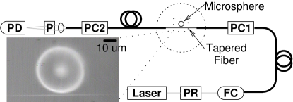
Space constraints in the chamber and limitations on the arrangement of the optical fiber caused bending of the fiber in different locations and subsequent scrambling of the input polarization. As a way to compensate for these changes in the polarization, we used two polarization controllers. The first one preceded the fiber taper, compensating for polarization changes up to the position of the microsphere. The second controller was placed after the fiber taper to ensure the linearity of the output polarization. Figure 1 shows a schematic of this experimental setup.
We used the following procedure to measure the degree of polarization conversion. First, the incoming polarization was selected by using the polarization rotator. Then we adjusted the first polarization controller to ensure the polarization at the fiber taper was linear and matched to one set of modes (“x-polarized”). The next step was to uncouple the taper from the sphere and make sure the output polarization was linear (we achieved this by turning the detection polarizer to its position for minimum transmission and then minimizing this transmission further with the second polarization controller). This orientation of the detection polarizer is the one we call “orthogonal”. Rotating the polarizer 90 degrees (the “parallel” orientation) resulted in maximum transmission, with a contrast of about 95%, confirming the linear polarization of the output light. Finally, we positioned the sphere and the tapered fiber trying to optimize the coupling, while measuring transmission spectra for both orientations of the detection polarizer. We repeated the procedure for two other incoming polarizations: one matched to the other set of sphere modes (“y-polarized”) and another at between the x- and y- polarization axis (“xy-polarized”).
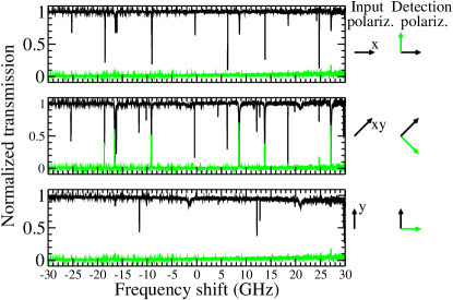
Figure 2 shows the resulting transmission spectra for the different configurations. The cases for both the x- and y- polarized light show the same behavior: a set of transmission dips whenever the laser frequency hit a whispering gallery resonance when the detection polarization is parallel and no signal when it is perpendicular. The xy-polarized case is more interesting: the parallel detection polarization shows dips for both sets of modes, while the orthogonal one shows transmission peaks at the whispering gallery resonances. At the highest peak, more than 70% of the incident light had its polarization converted.
Most of the observed polarization conversion can be understood by using a simple ring resonator model for the whispering gallery modes. In this model, the transmission of polarized light through the resonator is given bySmith et al. (2003); Cai et al. (2000)
| (1) |
where is the field coupling coefficient between the resonator and the waveguide, is the attenuation due to the resonator intrinsic losses and is the phase shift imposed by the resonator ( and are the incoming light frequency and the resonant frequency respectively, while is the round-trip time in the resonator). The model is scalar, but we can include the polarization by simply assuming that modes with orthogonal polarizations are independent and neglecting cross-polarized couplings (using an analysis similar to that by Little and ChuLittle and Chu (2000)). In this way we obtain the same expression, with possibly different parameters, for the transmission of both polarizations. In our particular case of whispering gallery modes in microspheres, we can safely assume that modes with different polarizations are not degenerate, so one of the polarizations will be unaffected by the presence of a resonance. This differs from the case of microringsMelloni et al. (2004), where the conversion depends on coupling between TE and TM modes.
The essence of the effect lies in the different resonator response for each polarization. For a strongly coupled fiber and microsphere, , but the phase shift is changed by as the frequency is sweeped across the resonance. Because the orthogonal polarization is transmitted unaltered, the transmitted polarization rotates by as much as for the initial xy-polarization. When the fiber and the resonator are horizontally stacked, the effect is maximized when the incident polarization is at degrees with respect to the horizontal plane.
Conversion efficiencies of up to 25% can be achieved if one of the polarizations is critically coupled to the ring, i.e. is completely absorbed in+the resonator. Achieving higher efficiencies requires increasing the resonator-waveguide coupling to obtain a significant polarization dependent phase shift which will change the final polarization state into one closer to the desired one.
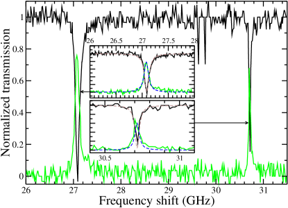
We can look in more detail at the data by concentrating into a pair of modes showing good conversion, now accounting for laser frequency drift between scans using a Fabry-Perot interferometer as a reference. This detailed spectrum can be seen in in Fig. 3. The resonance on the right side of Fig. 3, near a shift of 31 GHz, shows a polarization conversion of about 60%. The left-side resonance shows a conversion near 75%. The higher efficiency is due to the leftmost mode being more strongly coupled (displaying a broader feature) to the tapered fiber than the rightmost one. Consistent with theoretical predictions, in both cases one of the polarizations is over-coupled to the ring. The lack of a shift in the center frequency of the features also indicates that each pair of peak and dip corresponds to a single resonant mode.
This phenomenon could be useful for polarization control in photonic devices, such as narrowband polarization-dependent filtering or switching, as shown in Fig. 4 or even arbitrary polarization manipulation.

We have observed efficient polarization conversion on a microsphere resonator coupled to a tapered optical fiber and used a simple theoretical model to understand the phenomenon. The model does not involve direct coupling of the orthogonal polarizations, but rather a polarization-selective phase shift induced by the resonator. This effect should be common to all whispering gallery mode resonators and could be useful for polarization control in photonic devices.
Acknowledgements.
This work was supported by NSF-NIRT (DMR-0210383), the Texas Advanced Technology program, and the W.M. Keck Foundation. G.S. and C.F. acknowledge support from ARO MURI grant no. W911NF-04-01-0203.References
- Vahala (2003) K. J. Vahala, Nature (London) 424, 839 (2003).
- Matsko and Ilchenko (2006) A. B. Matsko and V. S. Ilchenko, IEEE J. Sel. Top. Quantum Electron. 12, 3 (2006).
- Gorodetsky et al. (1996) M. L. Gorodetsky, A. A. Savchenkov, and V. S. Ilchenko, Opt. Lett. 21, 453 (1996).
- Armani et al. (2003) D. K. Armani, T. J. Kippenberg, S. M. Spillane, and K. J. Vahala, Nature (London) 421, 925 (2003).
- Melloni et al. (2004) A. Melloni, F. Morichetti, and M. Martinelli, Opt. Lett. 29, 2785 (2004).
- Fomin et al. (2005) A. E. Fomin, M. L. Gorodetsky, I. S. Grudinin, and V. S. Ilchenko, J. Opt. Soc. Am. B 22, 459 (2005).
- Carmon et al. (2005) T. Carmon, H. Rokhsari, L. Yang, T. Kippenberg, and K. J. Vahala, Phys. Rev. Lett. 94, 223902 (2005).
- Park et al. (2006) Y.-S. Park, A. K. Cook, and H. Wang, Nano. Lett. 6, 2075 (2006).
- Cai and Vahala (2001) M. Cai and K. Vahala, Opt. Lett. 26, 884 (2001).
- Shopova et al. (2004) S. I. Shopova, G. Farca, A. T. Rosenberger, W. M. Wickramanayake, and N. A. Kotov, Appl. Phys. Lett. 85, 6101 (2004).
- Armani and Vahala (2006) A. M. Armani and K. J. Vahala, Opt. Lett. 31, 1896 (2006).
- Arnold et al. (2003) S. Arnold, M. Khoshsima, I. Teraoka, S. Holler, and F. Vollmer, Opt. Lett. 28, 272 (2003).
- Michelotti et al. (2003) F. Michelotti, A. Driessen, and M. Bertolotti, eds., Microresonators as building blocks for VLSI photonics, vol. 709 of AIP Conference Proceedings (American Institute of Physics, Melville, New York, 2003).
- Cai et al. (2000) M. Cai, O. Painter, and K. J. Vahala, Phys. Rev. Lett. 85, 74 (2000).
- Knight et al. (1997) J. C. Knight, G. Cheung, F. Jacques, and T. A. Birks, Opt. Lett. 22, 1129 (1997).
- Guan and Vollmer (2005) G. Guan and F. Vollmer, Appl. Phys. Lett. 86, 121115 (2005).
- Konishi et al. (2006) H. Konishi, H. Fujiwara, S. Takeuchi, and K. Sasaki, Appl. Phys. Lett. 89, 121107 (2006).
- Birks and Li (1992) T. A. Birks and Y. W. Li, J. Lightwave Technol. 10, 432 (1992).
- Weiss et al. (1995) D. S. Weiss, V. Sandoghar, J. Hare, V. Lefèvre-Seguin, J.-M. Raimond, and S. Haroche, Opt. Lett. 20, 1835 (1995).
- Smith et al. (2003) D. D. Smith, H. Chang, and K. A. Fuller, J. Opt. Soc. Am. B 20, 1967 (2003).
- Little and Chu (2000) B. E. Little and S. T. Chu, IEEE Photon. Technol. Lett. 12, 401 (2000).
- Almeida et al. (2004) V. R. Almeida, C. A. Barrios, R. R. Panepucci, and M. Lipson, Nature (London) 431, 1081 (2004).