Microscopic Treatment of Solute Trapping and Drag
Abstract
The long wavelength limit of a recent microscopic phase field crystal (PFC) theory of a binary alloy mixture is used to derive an analytical approximation for the segregation coefficient as a function of the interface velocity, and relate it to the two-point correlation function of the liquid and the thermodynamic properties of solid and liquid phases. Our results offer the first analytic derivation of solute segregation and solute drag derived from a microscopic model, and analytically support recent molecular dynamics and fully numerical PFC simulations. Our analytical result also provides an independent framework, motivated from classical density functional theory, from which to elucidate the fundamental nature of solute drag, which is still highly contested in the literature.
There are many theories explaining the morphologies and the underlying physics for near-equilibrium systems that evolve towards their equilibrium state Gollub and Langer (1999). By contrast, theories of physical phenomena associated with far-from-equilibrium systems remain much less developed. Rapid solidification from highly undercooled melts serves as a paradigm of such phenomena. In processes like laser-induced surface melting, spray forming, and welding among other technologies, highly super-saturated meta-stable solid solutions can form. In many cases, the non-equilibrium nature of such process can be exploited to control the degree of super-saturation of the solid.
At rapid-solidification rates, solute concentration at the solid-liquid interface (SLI) can deviate substantially from the values predicted by the equilibrium phase diagram, a phenomenon known as solute trapping Kittl et al. (2000); Aziz and Kaplan (1988); Galenko and Sobolev (1997); Ahmad et al. (1998); K. A. Jackson and Gudgel (2004); Sobolev (1995, 1997), In addition to solute trapping, the growth of a crystal with a composition differing from that of its melt requires solute diffusion to move across the SLI. The free-energy dissipation associated by interface diffusion leads to the phenomenon of solute drag, an effect which can strongly hinder the transformation rate. Solute drag arises due to a competition between interface diffusion rate and a chemical potential difference across the interface. When the velocity of the SLI is low, local equilibrium is assumed, the chemical potential difference between the SLI essentially vanishes, and solute drag is negligible. As the interface speed increases, solute diffusion limits the rate of partitioning across the interface (solute trapping), leading to an increasing chemical potential jump with velocity and, hence, an increasing solute drag. At large SLI speeds, solute partitioning eventually stops, as does diffusion of solute through the interface, and thus solute drag vanishes.
A phenomenology of solute drag was proposed in the seminal work by Cahn Cahn (1962) for the case of a grain boundary separating two solid phases. Although the Cahn model quantitatively predicts various aspects of the drag effect, it was assumed that the chemical potential is equal on both sides of the transformation front, an assumption that does not hold for a rapidly solidifying front. Later, Hillert and Sundman Hillert and Sundman (1976) incorporated a chemical potential jump into their phenomenology, and proposed that the maximum amount of free energy associated with drag is dissipated. A model for solute drag for solidification was first proposed by Hillert Hillert and Schalin (2000), which considered the structure of the interface and its effect on drag. Solute drag experiments are difficult to perform. Some show a significant change in solute concentration at the SLI interface at rapid solidification rates Smith and Aziz (1994), while some Kittl et al. (1995) even find no evidence of solute drag. Subsequent models proposed a partial solute drag hypothesis Aziz and Boettinger (1994a); Ahmad et al. (1998); Yang et al. (2011); Agren (1989). More recently, atomistic simulations of Yang et al Yang et al. (2011) and Humadi et al Humadi et al. (2013) proved that the solid-liquid interface stops partitioning solute at a finite velocity, consistent with predictions of Sobolev et al Sobolev (1995, 1997) and in contrast to earlier predictions of Aziz et al Aziz and Kaplan (1988); Aziz and Boettinger (1994a) with some evidence of partial solute drag.
Traditional phase field models of solidification consider bulk mass and heat transport coupled to moving interfaces through effective equilibrium boundary conditions Caginalp (1989); Caginalp and Socolovsky (1991); Karma and Rappel (1998); Provatas et al. (1998); Kim et al. (1999); Karma (2001); Boettinger et al. (2002); Echebarria et al. (2004) that map onto traditional sharp interface models. While such an approximation is appropriate at low solidification rates, it is inappropriate at rapid cooling rates where, as described above, non-equilibrium solute partitioning and drag become dominant. Based on the pioneering works of Cahn and Hillert Cahn (1962); Hillert and Sundman (1976); Hillert and Schalin (2000), modified sharp interface models were developed for rapid solidification Aziz and Boettinger (1994b, a). However, these models are largely phenomenological and are based on physically motivated, but often ad-hoc, parameters that cannot link the solidification kinetics to any microscopic quantity of the liquid and solid. More recent phase field modelling of rapid solidification has confirmed much of the phenomenology of these sharp interface models Kittl et al. (2000); Aziz and Kaplan (1988); Galenko and Sobolev (1997); Ahmad et al. (1998); K. A. Jackson and Gudgel (2004); Sobolev (1995, 1997). Still, no fundamental link between the meso-scale solidification process and the microscopic parameters of the materials can be made since solute trapping and drag fundamentally emerge at the atomic scale, where traditional phase field models, by their very nature, lack any qualitative and quantitative detail Echebarria et al. (2004); Provatas and Elder (2010). At present, no microscopic treatment of the trapping and solute drag coefficients entering rapid solidification models exists.
Recently, an emerging atomistic continuum modelling formalism coined the phase field crystal (PFC) method has been developed that presents an alternate atomistic framework with which phenomena such as solute trapping can be studied. In contrast to the traditional phase-field approach, PFC models are formulated in terms of order parameters that are periodic at the atomic scale, but whose dynamics evolve over diffusive time scales relevant to rapid solidification processes. A phase field crystal model of binary alloy solidification was first derived in Ref. Elder et al. (2007) as a simplification of a truncated density functional theory (DFT) expanded around the liquid state at coexistence. As such, the model inherits crucial microscopic liquid state parameters originating from the two-point correlation function of the solidifying liquid. The approach has been shown to self-consistently incorporate the physics of nucleation, multiple crystal orientations, grain boundary energy, elasto-plascitiy and topological defects and their dynamics Elder et al. (2002); Elder and Grant (2004); Berry et al. (2006); Stefanovic et al. (2006); Mellenthin et al. (2008); Stefanovic et al. (2009); Gránásy et al. (2011); Tegze et al. (2011). A significant advance in PFC modelling is its use with multi-scale and renormalization methods to project out meso-scale phase field models with complex order parameters Athreya et al. (2006, 2007); Huang et al. (2010), the coefficients of which maintain their connection to the microscopic liquid and solid state properties inherent in the generating PFC theory. In this letter, we use a PFC-dervied amplitude model of solidification to elucidate, for the first time, an analytical derivation of the non-equilibrium solute partition coefficient and the solute drag coefficient that enters models of solute drag.
Multiple scale analysis applied to the PFC alloy model in Elder et al. (2007) yields the following moving front equations for the impurity concentration () and the amplitude of the reduced atomic number density ) Humadi (2013),
| (1) | |||||
Their derivation assumes that the atomic number density is represented by , where is the reduced average alloy density, and is the reference liquid density at coexistence. It is assumed that here for simplicity. The is the reciprocal lattice vector of a general multi-mode expansion of the density, and is the complex density amplitude corresponding to the density wave. We consider here a 2D triangular crystal structure but the qualitative physics of our results are not expected to change for other crystal structures. For solidification, it is suitable to set all the to be real, i.e. . The equations are written in a co-moving 1D reference frame moving at velocity , which is accurate for rapid solidification. The second order derivatives allow for a two-time scale relaxation of the density and concentration fields. They can be motivated by considering mass and momentum conservation of two-species densities and Stefanovic et al. (2006); Majaniemi and Grant (2007); Humadi et al. (2013). The coefficients and are microscopic relaxation parameters for the solute and density, respectively, while is the mobility of impurity atoms. The variable , where is the local interface normal vector and is the lowest order coefficient of the solid compressibility. The liquid compressibility is denoted by and expanded as Elder et al. (2007). The bulk free energy is denoted by and , where . The variables are the respective coefficients of the bare , , and terms of a landau expansion of the bulk free energy. Bulk compressibility of the liquid , and , where are coefficients of a fourth order expansion of the two-point correlation function of the liquid state, given by Elder et al. (2007). In what follows, we rescale and , where and are the bulk order parameter and concentration of the solid phase, respectively. All results presented here are for .
For the parameters above, the equilibrium partition coefficient of the PFC model of Ref.Elder et al. (2007) is . The solidus-to-liquidus jump for this model is , which forms an ideal small parameter to expand . Notice that in the PFC model, with a quite high value of , the paramter is indeed very small. Nevertheless, the jump in concentration between liquid and solid is small in most alloy system and thus we anticpate the results derived below to be applicable in general. Integrating the equation in Eq. 1 from to and substituting into the result gives the following equation for ,
| (2) |
Equation 2 will be used to approximate the concentration profile in the liquid. Higher order terms are needed to approximate concentration in the solid, but that will not be necessary here and will be omitted in what follows.
In Eq. 1 the parameter is a measure of the SLI width and therefore we approximate the order parameter , and define , where , as the interface between solid and liquid ordering analogous to molecular dynamics studies Yang et al. (2011). is is the exact lowest order solution of the PFC model for a pure material P. K. Galenko and Elder (2014). We have found that it is also a reasonable approximation for the density amplitude of the PFC alloy model. Substituting the above expression for into Eq. (2) gives,
| (3) |
where and . This equation can be solved analytically with an integrating factor that must be solved numerically. In favour of obtaining a tractable analytic expression to work with, we exploit the fact that and and seek an analytical solution to lowest order in . This gives,
| (4) |
where . In obtaining Eq. (4), the integration constant was found by applying the boundary condition at , where is the equilibrium liquid concentration, and defines the point where the concentration profile reaches a maximum, consistent with molecular dynamics Yang et al. (2011) and previous PFC alloy simulations Humadi et al. (2013). We also take the far field concentration in the liquid to be the same as the solid concentration . For simplicity, we analyze only the exponential part of Eq.(4). We found that including the higher order terms gives essentially the same results.
The segregation coefficient is defined to be the ratio of the interface solid concentration to that of the maximum liquid concentration, which occurs when at . In the PFC model, the concentration is expanded around , which yields negative concentrations on the left side of the phase diagram. As a result, the solute partition coefficient for the PFC alloy model is defined as
| (5) |
Figure (1) plots for two cases, the first case (purple curve online) for and the second case (blue curve online) for . For the first case at a finite , while in the second case, only asymptotically as the solid-liquid interface velocity .
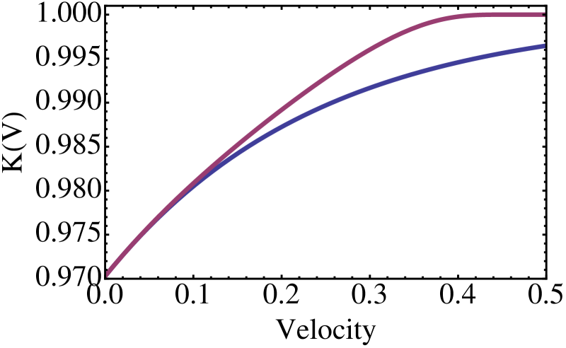
There are two competing theories for explaining in the literature. The first, by Aziz Aziz and Kaplan (1988) assumes purely diffusive solute transport and flux balance across the interface to predict the segregation coefficient. Aziz predicts that approaches complete trapping () asymptotically, and never reaches unity at finite . More recently, Sobolev Sobolev (1995, 1997) proposed a phenomenology that considered inertial dynamics of solute atoms in the liquid. This lead to the emergence of an effective diffusion coefficient, which makes it possible for to reach unity at a finite velocity.
In our microscopic PFC formalism, the constant in Eq. 4 emerges as an effective diffusion coefficient. The value of decreases to zero as the interface velocity increases. As a result, the liquid concentration tends to the solidus concentration. However, this is only true for non-zero inertial solute relaxation time (). Otherwise, always remains non-zero, and does not change the classical diffusive nature of the concentration profile. This allows for a concentration jump to develop across the two sides of the interface, even for arbitrarily large interface velocities().
The above analytical PFC result is consistent with the previous numerical simulations of the alloy PFC model Humadi et al. (2013) as well as with recent molecular dynamics simulations Yang et al. (2011). We note that a higher order perturbation analysis of the coupled Eqs. (1) would be required to compare the results quantitatively with the full numerical simulations. However, the physics does not change. Our result is the first solute trapping theory to offer a prediction of the complete solute trapping velocity in terms of microscopic parameters. Namely, Eq. (4) predicts that complete trapping occurs when . The approximate form of was derived in Ref. (Elder et al. (2007)), given by: , where the variables in this expression are given by , , , while and . Thus, we have shown that the complete trapping velocity is inversely proportional to the square root of the inertial relaxtion tme and proportion to , which is determined by the properties of the two-point correlation function of the liquid , through , and the bulk solid free energy density, through ().
Solute drag in the context of the PFC formalism can also be elucidated using Equation (4). The theoretical formalism of solute drag is briefly summarized here. The free energy density available for solidification of a binary alloy (denoted here as ) is partially dissipated due to solute atoms diffusively redistributing parallel to the solidifying front before attaching to the solid phase. This dissipation is referred to as solute drag, and reduces the total effective free energy available for solidification (denoted ) to
| (6) |
where the maximum drag was shown by Ahmad et al to be Ahmad et al. (1998), while , derived by Cahn Baker and Cahn (1971), where denotes bulk free energy density and and are the inter-diffusional chemical potentials of the liquid and solid phase and evaluated at and , which are, respectively, the liquid and solid concentrations on the liquid and solid side of the interface. We can equivalently express , where () are the solvent (solute ) chemical potential differences between the solid and liquid phases. The important constant has limits , with implying zero drag maximum drag. We determine in the PFC formalism below.
The above expressions for and were applied by Ahmad and co-workers Ahmad et al. (1998) to a phenomenological phase-field model. Since the PFC amplitude equations (1) are also a phase-field theory, derived by coarse graining a microscopic PFC theory, we similarly apply the above expressions to the free energy of the PFC amplitude model. This is derived from , which in the bulk gives
| (7) |
for the free energy density in the solid () and liquid ().
At low thermodynamic driving forces, molecular dynamics simulations and experiments suggest that Turnbull (1962), a relation that becomes less accurate near complete trapping velocities. The solute drag coefficient in Eq. (6) can thus be determined by tuning until a linear relationship between and emerges. We do so here numerically. To proceed, the solid concentration and order parameter are assumed constant in the solid during steady-state front propagation, while the liquid concentration is determined by Eq. 4. These quantities are substituted into and to compute , and . Fig 2a shows three different cases of versus . The blue line represents the diffusive case where no complete trapping occurs (). The purple and the yellow lines show for and , respectively.
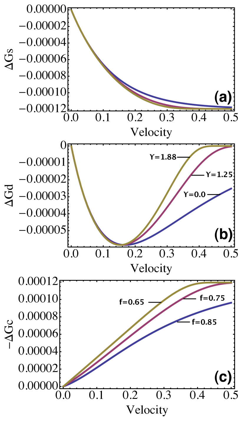
Fig 2b plots for the same values as Fig 2a. It is noteworthy that the maximum amount of solute drag (minimum of ) does not change as the degree of trapping () changes. However, the curvature of at large is quite sensitive to . This occurs because as increases, complete trapping occurs at lower velocity (). This causes the concentration difference across the interface to decrease rapidly for , thus leading to a decrease in , which depends on . Fig 2c shows that for each , the partial solute drag fraction exists for which at low SL velocities. This confirms previous solute drag phenomenologies, and is consistent with recent molecular dynamics results Yang et al. (2011). Our results illustrate that as the solute relaxation coefficient changes , and the degree of solute trapping, it also affects the driving force for complete crystallization through and the solute drag coefficient .
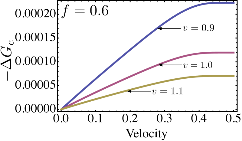
Other materials parameters of our phase field crystal theory were also examined for their effect on solute drag. An important one is the equilibrium solute partition coefficient , which is controlled by , the coefficient of the term in the bulk PFC free energy functional. Increasing leads to increasing . Materials with larger exhibit lower complete trapping velocities () because less driving force is required to reach complete trapping for a decreasing concentration jump . Thus, solute drag also decreases as increases. Interestingly, while changes the maximum available solute drag (), we found that it does not change the partial solute drag coefficient . Fig 3 illustrates Vs. for three values of (or, equivalently, ), at a fixed (other parameters are as indicated at the beginning of this paper). For all curves in Fig 3, the value of is the same. This illustrates that in all cases, the driving force for crystallization () increases as solute drag decreases because of the decreasing of , not because is changing. This important prediction implies that solute drag is strictly a kinetic process (i.e. depends on , through ) and that is a thermodynamic quantity that has no effect on the maximum solute drag.
In summary, an amplitude model derived from a microscopic phase field crystal model has been derived to study the phenomena of solute trapping and solute drag, two important materials processes that remain poorly understood. We have derived a first order analytic expression for the concentration profile in the liquid as a function of interface velocity and position, and used it to derive the solute trapping coefficient . Our model predicts that when inertial dynamics are included in solute transport, complete trapping occurs at a finite velocity, consistent with the phenomenology of Sobolev Sobolev (1995, 1997) and recent MD simulations. A key result is the derivation of an expression for the complete trapping velocity as a function of the bulk compressibility of the solid and liquid and the bulk free energy of each phase.
In addition, we used our result for to elucidate the role of the solute drag coefficient. Partial solute drag is predicted for a solidifying front in the context of the PFC model. As increases, the maximum solute drag decreases proportionately to the complete trapping velocity and solute relaxation time. The larger the solute relaxation parameter (), the lower the complete trapping velocity and therefore the smaller the amount of solute drag (). For fixed , the PFC model predicts a linear relationship between interface velocity and the total free energy for crystallization, consistent with recent MD simulations. It was found that the total available free energy for solidification and the maximum solute drag are velocity dependent, while the partial solute drag coefficient was independent of the velocity. Model parameters such as those that alter the equilibrium segregation coefficient () were also examined. It was found that as increases, complete trapping occurrs at slower velocities due to lower driving forces required by the system. This also changes the maximum available solute drag, but, again, does not affect the solute drag coefficient .
The results of this work comprise the first independent predictions of solute trapping and drag concepts emerging from a continuum theory that is fundamentally derived from a microscopic density functional theory. As a result, the analytical and numerical results presented here can be related to both thermodynamic material properties of the solid and liquid, as well as to the microscopic correlation properties of the melt from which crystallization occurs.
The authors would like to acknowledge the National Science and Engineering Research Council of Canada (NSERC) for the finical support of this work.
References
- Gollub and Langer (1999) J. P. Gollub and J. S. Langer, Rev. Mod. Phys. 71, S396 (1999).
- Kittl et al. (2000) J. A. Kittl, P. G. Sanders, M. J. Aziz, D. P. Brunco, and M. O. Thompson, Acta Mater. 48, 4797 (2000).
- Aziz and Kaplan (1988) M. J. Aziz and T. Kaplan, Acta Metall. 36, 2335 (1988).
- Galenko and Sobolev (1997) P. Galenko and S. Sobolev, Phys. Rev. E 55, 343 (1997).
- Ahmad et al. (1998) N. Ahmad, A. Wheeler, W. Boettinger, and G. McFadden, Phys Rev E 58, 3436 (1998).
- K. A. Jackson and Gudgel (2004) K. M. B. K. A. Jackson and K. A. Gudgel, J. Cryst. Growth 271, 481 (2004).
- Sobolev (1995) S. L. Sobolev, Phys. Rev. A 199, 383 (1995).
- Sobolev (1997) S. L. Sobolev, Phys. Rev. E 55 (1997).
- Cahn (1962) J. W. Cahn, Acta. Metall. 10, 789 (1962).
- Hillert and Sundman (1976) M. Hillert and B. Sundman, Acta Metall 24, 731 (1976).
- Hillert and Schalin (2000) M. Hillert and M. Schalin, Acta Materialia 48, 461 (2000), qC 20100525.
- Smith and Aziz (1994) P. Smith and M. J. Aziz, Acta Metall. 42 (1994).
- Kittl et al. (1995) J. A. Kittl, M. J. Aziz, D. P. Brunco, and M. O. Thompson, J. Cryst. Growth 148, 172 (1995).
- Aziz and Boettinger (1994a) M. J. Aziz and W. J. Boettinger, Acta Metall. Mater. 42 , 257 (1994a).
- Yang et al. (2011) Y. Yang, H. Humadi, D. Buta, B. B. Laird, D. Sun, J. J. Hoyt, and M. Asta, Phys. Rev. Lett. 107, 025505 (2011).
- Agren (1989) J. Agren, Acta Metall. 37, 181 (1989).
- Humadi et al. (2013) H. Humadi, J. J. Hoyt, and N. Provatas, Phys. Rev. E 87, 022404 (2013).
- Caginalp (1989) G. Caginalp, Phys. Rev. A 39, 5887 (1989).
- Caginalp and Socolovsky (1991) G. Caginalp and E. Socolovsky, SIAM J. Sci. Comp. 15, 106 (1991).
- Karma and Rappel (1998) A. Karma and W. J. Rappel, Phys. Rev. E 57, 4323 (1998).
- Provatas et al. (1998) N. Provatas, N. Goldenfeld, and J. Dantzig, Phys. Rev. Lett. 80, 3308 (1998).
- Kim et al. (1999) S. G. Kim, W. T. Kim, and T. Suzuki, Phys. Rev. E 60, 7186 (1999).
- Karma (2001) A. Karma, Phys. Rev. Lett 87, 115701 (2001).
- Boettinger et al. (2002) W. Boettinger, J. Warren, C. Beckermann, and A. Karma, Annu Rev. Mater. Res. 32, 163 (2002).
- Echebarria et al. (2004) B. Echebarria, R. Folch, A. Karma, and M. Plapp, Phys. Rev. E. 70, 061604 (2004).
- Aziz and Boettinger (1994b) M. J. Aziz and W. J. Boettinger, Acta Metall. 42, 527 (1994b).
- Provatas and Elder (2010) N. Provatas and K. Elder, Phase-Field Methods in Materials Science and Engineering (Wiley-VCH Verlag GmbH & Co. KGaA, 2010), ISBN 9783527631520.
- Elder et al. (2007) K. R. Elder, N. Provatas, J. Berry, P. Stefanovic, and M. Grant, Phys. Rev. B. 75, 064107 (2007).
- Elder et al. (2002) K. R. Elder, M. Katakowski, M. Haataja, and M. Grant, Phys. Rev. Lett. 88, 245701 (2002).
- Elder and Grant (2004) K. R. Elder and M. Grant, Phys. Rev. E 70, 051605 (2004).
- Berry et al. (2006) J. Berry, M. Grant, and K. R. Elder, Phys. Rev. E 73, 031609 (2006).
- Stefanovic et al. (2006) P. Stefanovic, M. Haataja, and N. Provatas, Phys. Rev. Lett. 96, 225504 (2006).
- Mellenthin et al. (2008) J. Mellenthin, A. Karma, and M. Plapp, Phys. Rev. B 78, 184110 (2008).
- Stefanovic et al. (2009) P. Stefanovic, M. Haataja, and N. Provatas, Phys. Rev. E 80, 046107 (2009).
- Gránásy et al. (2011) L. Gránásy, G. Tegze, G. I. Tóth, and T. Pusztai, Philosophical Magazine 91, 123 (2011).
- Tegze et al. (2011) G. Tegze, G. I. Toth, and L. Granasy, Phys. Rev. Lett. 106 (2011).
- Athreya et al. (2006) B. P. Athreya, N. Goldenfeld, and J. A. Dantzig, Phys. Rev. E 74, 011601 (2006).
- Athreya et al. (2007) B. P. Athreya, N. Goldenfeld, J. A. Dantzig, M. Greenwood, and N. Provatas, Phys. Rev. E 76, 056706 (2007).
- Huang et al. (2010) Z.-F. Huang, K. R. Elder, and N. Provatas, Phys. Rev. E 82, 021605 (2010).
- Humadi (2013) H. Humadi, Ph.D. thesis, McMaster Univeristy (2013).
- Majaniemi and Grant (2007) S. Majaniemi and M. Grant, Phys. Rev. B 75, 054301 (2007).
- P. K. Galenko and Elder (2014) F. I. S. P. K. Galenko and K. R. Elder, Physica D Preprint (2014).
- Baker and Cahn (1971) J. C. Baker and J. W. Cahn, in Solidification (1971), ASM, p. 23.
- Turnbull (1962) D. Turnbull, J. Phys. Chem. 66 (1962).