Positive feedback and temperature mediated molecular switch controls differential gene regulation in Bordetella pertussis
Abstract
Based on the phosphorelay kinetics operative within BvgAS two component system we propose a mathematical framework for signal transduction and gene regulation of phenotypic phases in Bordetella pertussis. The proposed model identifies a novel mechanism of transcriptional interference between two promoters present in the bvg locus. To understand the system behavior under elevated temperature, the developed model has been studied in two different ways. First, a quasi-steady state analysis has been carried out for the two component system, comprising of sensor BvgS and response regulator BvgA. The quasi-steady state analysis reveals temperature induced sharp molecular switch, leading to amplification in the output of BvgA. Accumulation of a large pool of BvgA thus results into differential regulation of the downstream genes, including the gene encoding toxin. Numerical integration of the full network kinetics is then carried out to explore time dependent behavior of different system components, that qualitatively capture the essential features of experimental results performed in vivo. Furthermore, the developed model has been utilized to study mutants that are impaired in their ability to phosphorylate the transcription factor, BvgA, of the signaling network.
keywords:
Mathematical model , signal transduction , steady state analysis , two component system , phenotype1 Introduction
One of the important functional aspects of living organisms is to respond to the sudden changes made in their environment, and to make appropriate changes in the cellular or subcellular level for survival. Direct manifestations of such changes at the subcellular level are the expression/repression of single or multiple genes controlling different functional behavior of an organism (Alon, 2007). To achieve this, living system utilizes concerted biochemical network composed of several feedback mechanism (Tyson et al., 2003; Tyson and Novák, 2010). The human pathogen Bordetella pertussis, a gram negative bacteria and causative agent for the disease whooping cough (Preston et al., 2004), is no exception to the aforesaid behavior. At 25 ∘C, while freely moving in the environment their pathogenic properties remain dormant. But, when they are within the host at 37 ∘C, their virulent properties come into play. In the laboratory the reverse effect, i.e., suppression of pathogenic behavior is observed using MgSO4 or nicotinic acid (Beier and Gross, 2008; Cotter and Jones, 2003). The virulent behavior of B. pertussis within host, in response to sudden environmental change, has been experimentally studied and has been found to be operative through BvgAS two component system (TCS) (Beier and Gross, 2008; Cotter and Jones, 2003). The TCS comprises of transmembrane sensor BvgS and response regulator BvgA where signal flows through this pair via a four step (His-Asp-His-Asp) phosphorelay mechanism.
As a response to temperature elevation in the environment, the response regulator BvgA becomes active (the phosphorylated dimer) within each bacterium, which in turn exerts a positive feedback on its own operon, the bvg operon. Positive feedback loop thus increases the active form of BvgA in a switch like manner. In other words, once the BvgAS two-component machinery becomes operative, large pool of active BvgA either repress and/or express several downstream genes where the phosphorylated dimer of BvgA plays the leading role by acting as transcription factor (TF) (Steffen et al., 1996). In the laboratory condition at 37 ∘C and in the absence of MgSO4 or nicotinic acid BvgA activates transcription of virulence activated genes (vag), as well as represses transcription of virulence repressed genes (vrg). Due to this reason bvg locus was earlier called vir due to its connection to virulence (Beier and Gross, 2008; Cotter and Jones, 2003; Weiss and Falkow, 1984). In B. pertussis, vrg loci encodes outer membrane whereas in B. bronchiseptica, vrg controlled genes encode motility and survival from nutrient limitation condition. In Bordetella spp., vag loci encodes genes responsible for adherence, toxins (including pertussis toxin in B. pertussis, a type III secretion system and BvgAS itself (due to autoregulation).
Based on the binding affinity of TF to the respective promoters, different types of downstream genes are regulated in Bordetella spp. and have been broadly grouped into four classes, e.g., class 1, class 2, class 3 and class 4 (Beier and Gross, 2008; Cotter and Jones, 2003). Class 1 genes encompass genes that are responsible for encoding toxins, such as adenylate cyclase (cyaA-E) and pertussis toxin (ptxA-E). Class 2 genes express proteins responsible for adherence, such as fhaB that encodes filamentous hemagglutinin. Among all the four classes of genes, class 3 genes show a unique behavior, although its functional activity is not known till date (Beier and Gross, 2008; Cotter and Jones, 2003). The only well characterized class 3 gene found in B. pertussis is known as bipA. The final one, class 4 genes have been reported to encode frlAB in B. bronchiseptica and is responsible for motility. It is important to mention that expressions of class 3 and class 4 gene are not observed in B. pertussis under the influence of temperature elevation. To be specific, class 3 gene expression has been observed in B. pertussis only under the influence of intermediate concentration of MgSO4 and class 4 gene under low concentration of MgSO4 in B. bronchiseptica (Beier and Gross, 2008; Cotter and Jones, 2003). In terms of vir regulated genes class 4 gene thus belongs to vrg whereas class 1 and class 2 genes belong to vag. Expression and/or repression of the four classes of downstream genes is controlled by strong and/or weak binding sites (for TF) present in the promoter region of the respective genes. Among these, promoter region of class 4 gene has the strongest affinity for TF. Promoter region of class 2 and class 3 genes have medium affinity for TF, whereas promoter region of class 1 gene has the weakest affinity for TF. On the basis of the promoter regions’ affinity for TF it is thus expected that expression and/or repression of four classes of downstream genes in Bordetella spp. would show a differential pattern in their temporal dynamics.
Keeping these aforesaid phenomenological information in mind we have developed a mathematical model based on biochemical interactions taking place within B. pertussis under the influence of temperature elevation. The objective of present work is twofold. First, we aim to understand the molecular switch operative in BvgAS TCS and to identify the key players responsible for amplification of TF. Second, through our model we aim to regenerate qualitative features of the network and to mimic different phenotypic states of B. pertussis under temperature elevation, as well as their expression level due to different mutation.
2 The Model
To understand the mechanism for temperature induced activation of bvg locus and differential regulation of the downstream genes, we propose a kinetic model in the following.
2.1 The bvg locus
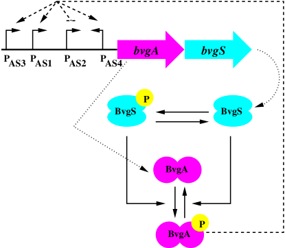
Experimental studies in B. pertussis suggest multi-promoter activities in bvg operon (Roy et al., 1990; Scarlato et al., 1990, 1991). Out of the four promoters, , , and , present in the bvg locus (see Figure 1), only is known to be constitutively active under non-inducing condition (25 ∘C) and is bvg independent. After induction (37 ∘C), activity of the promoter goes down while the other three promoters (, and ) become active. As shown in Scarlato et al. (1991), at 37 ∘C, shows maximal level of activity compared to and is on within minutes of induction. The amount of transcripts generated from is very low and have been reported to be hardly detectable. The promoter shows same level of activity as but produces antisense RNA. Although activity of promoter and its product, the antisense-RNA, is known, the target of the antisense RNA is not known till date. In passing it is important to mention that multi-promoter activity in the operon of TCS as observed in B. pertussis, has also been observed in other human pathogens (Chauhan and Tyagi, 2008; Donà et al., 2008).
To study functioning of the bvg locus we consider only the activity of two the promoters and in our model, as reasonable amount of experimental data is available in the literature for these two promoters (Scarlato et al., 1991). Both these promoters are typical example of tandem promoter, containing a conserved region of base pairs between upstream of and transcriptional start site (TSP) of . In the model, we designate the constitutive form of under non-inducing condition as . Once induced, TF interacts with both and and makes them active
| (1) | |||||
| (2) |

In the above equations is the active form of ; and and are inactive and active form of promoter, respectively. Due to the presence of conserved region of base pairs, RNA polymerase (RNAP) for traversing through downstream of now interferes with the binding of TF (and RNAP for ) to upstream of causing transcriptional interference (see Figure 2) (Buetti-Dinh et al., 2009; Shearwin et al., 2005). During this process and act as sensitive and aggressive promoter, respectively. Although a detailed kinetic mechanism of transcriptional interference has been proposed and verified experimentally (Buetti-Dinh et al., 2009), we use the following notion to keep the model simple
| (3) |
where the information of upstream inhibition are put together in the rate constants. The rate constant in Eq. (3) contains the information of RNAP coming from causing transcriptional interference at ,
Considering the pool of RNAP to be constant one can absorb it into the overall rate of the interference mechanism and write , the overall rate constant of the interference process given in Eq. (3). After causing the interference the RNAP coming from falls off from thus giving chance to the later to back to the active form again, which is modeled as the backward reaction with rate constant in Eq. (3). This helps the promoter to maintain a low activity even after 2 hours of induction as evident from the experimental data (see Figure 3B of Scarlato et al. (1991) and Figure 6 of the present work). To keep track of the transcripts generated due to and , following Scarlato et al. (1991), we consider two isoforms of mRNA generated from the bvg locus, and , respectively. At 25 ∘C, is constitutively produced from the constitutive state of promoter
| (4a) |
After 2 hours of induction, level of goes down but still maintains a low level of expression (see Figure 3B of Scarlato et al. (1991)) which we assign to the residual activity of . After 20 minutes of induction, production of remains still on, reaches a maxima, and then goes down which we attribute to the suppression of and the formation of altogether. Thus after induction,
| (4b) |
Unlike the transcripts generated due to activity, generation of is solely governed by the active form of promoter
| (5) |
Finally, we consider natural degradation of both the transcripts generated from and ,
| (6) |
2.2 The two component system
Once transcribed from the locus, we consider translation of two isoforms and into dimers of sensor, BvgS (), and response regulator, BvgA () proteins,
| (7a) | |||
| (7b) | |||
| (7c) | |||
| (7d) | |||
In reality the sensor and response regulator proteins are first translated as monomers and then dimerize (Beier and Gross, 2008). Since dimers of BvgA, not the monomers, act as transcription factors for the activation of bvg locus, we have omitted kinetics of monomer formation and subsequent dimerization in our model and work instead with and . As we show in the following, this simplification does not affect our analysis and modeling of the signal transduction network.
In bacterial TCS, autophosphorylation occurs at histidine residue of the sensor kinase, that serves as source of phosphate group and transfers the same to the aspartate residue of response regulator, acting as sink (Appleby et al., 1996; Hoch, 2000; Laub and Goulian, 2007; Mitrophanov and Groisman, 2008; Stock et al., 2000). This orthodox two-step His-Asp phosphotransfer becomes complicated in B. pertussis where signal transduction takes place via a unorthodox four-step His-Asp-His-Asp phosphotransfer mechanism (Uhl and Miller, 1996), where the first three steps (His-Asp-His) take place within the sensor protein BvgS and in the last step (His-Asp) phosphate group flows from the transmembrane sensor BvgS to the cytoplasmic response regulator BvgA. Mathematical modeling of two-step phosphorelay has been reported in different context of bacterial signal transduction (Banik et al., 2009; Batchelor and Goulian, 2003; Kato et al., 2007; Kierzek et al., 2010; Kremling et al., 2004; Shinar et al., 2007; Sureka et al., 2008). Whereas mathematical modeling of four-step phosphorelay has been extensively used for the gram positive bacteria Bacillus subtilis to understand the sporulation initiation, a detailed account of which can be found in the recent review by Liebal et al. (2010). In B. subtilis the external signal is sensed by a family of five histidine kinase KinA-E and finally transferred to the response regulator Spo0A via Spo0F and Spo0B. Phosphorylated Spo0A acts as a TF by controlling over 500 genes (Fawcett et al., 2000) which are broadly classified into two categories by the affinity of Spo0A to their target genes (Fujita et al., 2005). In passing we would like to mention the work by Kim and Cho (2006) where a comparative study of two-step versus four-step phosphorelay has been undertaken. In the present study we have adopted a simplified approach of what is proposed by Kim and Cho (2006). Instead of detailed three-step (His-Asp-His) phosphotransfer mechanism within BvgS we consider autophosphorylation at , the dimer of BvgS,
| (8) |
While writing the above equation we have put the information of ATP and its interaction with the sensor protein in the rate constant ; In addition it is a function of input signal which may be temperature or salt concentration for B. pertussis. In absence of any signal, , autophosphorylation at the histidine residue becomes nonfunctional, i.e., . At this point it is important to mention that exact mechanism for the activation of BvgS in B. pertussis under temperature induction is not clear from the literature. To incorporate sensing of the external stimulus and subsequent activation of the TCS we have adopted the mechanism given in 8. Once phosphorylated the sensor protein transfers the phosphate group to their cognate response regulator , the dimer of BvgA, mimicking the last step (His-Asp) of the four-step phosphotransfer mechanism
| (9) |
where is the Michaelis complex formed by and . In addition to their kinase activity the sensor protein also exhibits phosphatase activity by removing the phosphate group from their cognate partner (Batchelor and Goulian, 2003; Laub and Goulian, 2007; Shinar et al., 2007) thus showing bifunctional behavior
| (10) |
Likewise the mRNA transcribed from the bvg locus, we consider natural degradation of different forms of sensor and response regulator proteins
| (11) |
The phosphorylated dimer of the response regulator then exerts a positive feedback in the bvg locus thus activating the promoters of the locus (see Eqs. (1-2)). In addition they control the expression and/or repression of several downstream genes.

2.3 Differential gene regulation
To model regulation of downstream genes under induced condition we use the following TF binding properties of different promoters of downstream genes. The promoters for class 1 gene contain low affinity BvgA binding site far upstream of the TSP, as a result high level of is necessary to activate these genes and they are expressed quite late compared to class 2 and class 3 genes. Class 2 promoters contain high affinity BvgA binding site close to TSP and fairly low level of is sufficient to activate these genes. As a result, expression of class 2 genes becomes visible within very short period after induction. Class 3 gene, bipA, contains high affinity as well as low affinity BvgA binding site just upstream and downstream of TSP, respectively. Once induced, bipA becomes active almost at the same time like fhaB (class 2 gene) with the help of low amount of . At a critical concentration of BvgA gene expression becomes maximum and then it starts falling due to BvgA binding to the downstream low affinity binding site. The frlAB promoter (class 4) has been found to contain distinguishable BvgA binding site that overlaps with TSP (Akerley et al., 1995). Thus a very low level of BvgA may be able to suppress class 4 genes.
In Figure 3 we schematically show regulation of four classes of genes as BvgA level increases. The binding kinetics of phosphorylated dimer of BvgA () to the promoters of these four classes of genes are given in the Supplementary data. While active, four classes of genes starts transcribing their corresponding mRNA
| (12) |
where . Likewise the transcripts generated from the bvg locus, we consider natural degradation of the four different classes of transcripts
| (13) |
Before proceeding further we would like to mention that all the relevant symbols designating biochemical species used in this section are listed in Table 1.
3 Results and Discussions
To check the validity of our proposed model, the kinetic network developed in the previous section has been translated into sets of coupled nonlinear ordinary differential equations (ODEs). To understand functionality of temperature induced switch operative in the proposed model we first analyze the kinetics for bvg locus and the TCS using quasi-steady state approximation (Batchelor and Goulian, 2003). The full network kinetics is then numerically integrated for large set of parameters of the proposed model and compared with in vivo experimental results (Scarlato et al., 1991).
3.1 Steady state analysis
According to the model described in the previous section total amount of sensor and response regulator proteins can be expressed by the following relations
| (14) | |||||
| (15) |
where (see Table 2). Thus one can express essential features of the dynamics in terms of the response regulator protein. To realize the nature of amplification in gene expression at 37 ∘C and to analyze the steady state dynamics we divide the TCS signaling network into two modules, the autoregulation module and the phosphorylation (or post-translational) module.
Before proceeding further we would like to comment on the input-output relation in the present model. For this, we define the influx and outflux of phosphate group in the network as
respectively (Shinar et al., 2007). Using the steady state expression of (see Eq. (35) of the Appendix 5.4) and considering at steady state, one arrives at . Thus, the steady state output of TF in the present model is dependent on the input signal and the phosphatase activity of the sensor kinase on the response regulator. For further analysis we have removed the superscript from the steady state expressions for notational simplicity.

3.1.1 Autoregulation module
Autoregulation module takes care of synthesis and degradation of TF mediated by positive feedback loop operative within bvg operon. This ultimately leads into total amount of response regulator, , expressed in terms of the TF, , in the steady state. To derive such expression we take time derivative of Eq. (15) and impose quasi-steady state condition on and (see Appendix 5.4) thus leading into
| (16) | |||||
which finally yields the desired functional relationship between and
| (17) | |||||
where . The first two terms on the right hand side of Eq. (17) arise due to promoter activity whereas the third term is solely due to promoter under inducing condition. In the limit of zero phosphorylation (), i.e., at 25 ∘C, Eq. (17) leads to . Thus, under zero stimulus system dynamics is solely governed by basal transcription () and translation () processes.
3.1.2 Phosphorylation module
Considering only the phosphotransfer kinetics (see Eqs. (8-10)) and using the relations given in the Eq. (35) of Appendix 5.4 we have at steady state
| (18) | |||
| (19) |
While deriving the above two expressions we have again imposed quasi-steady state condition on the two Michaelis intermediates and . After some algebra Eqs. (18-19) provide
| (20) |
where and . Now, for , Eq. (20) gets transformed into
| (21) | |||||
which is valid for . Thus steady state output of depends on both and the source of autophosphorylation, . For , Eq. (21) yields . Since is a function of , for fixed set of other parameters of the model, a change in brings in a change in the value of . In addition, level does not depend on anymore but remains dependent on ATP level through the rate constant .
In Figure 4 we show functional relation between normalized and normalized at steady state (Miyashiro and Goulian, 2008). Normalization was done with respect to the total amount of response regulator (phosphorylated and unphosphorylated) at steady state. At steady state, depending on the level of input stimulus (here temperature of the environment), total amount of BvgA protein, , exists either in phosphorylated form () or in un-phosphorylated form () of which only the phosphorylated form acts as TF. The level of at steady state is controlled by both the external temperature and the total amount of available BvgA protein. At low temperature only a small amount of gets transformed into which increases as the temperature of the environment is raised. Enhancement of level out of the total pool due to temperature elevation is shown by the two sigmoidal solid curves in Figure 4 using Eq. (21). It is interesting to note that even when a large pool of is available to be phosphorylated only a small amount gets transformed into at low temperature due to low autophosphorylation rate () of Bvgs. But, at high temperature high value changes the scenario by increasing the level (see the discussion on amplification in subsection 3.2).
Formation of pool of due to temperature elevation does not work due to phosphotransfer mechanism only. It works hand in hand with the autoregulation module as well. As mentioned earlier, in the absence of external stimulus () the only form of BvgA available is that leads to . This gives the basal expression level (the left most vertical dotted line) in Figure 4. As the system gets switched on () gets generated due to phosphotransfer and provides a positive feedback on the bvg operon. Positive feedback enhances the production of which are ready to be phosphorylated at a fixed stimulus. This essentially increases the amount of out of . This functional relation between and due to autoregulation is given by Eq. (17) and is plotted in Figure 4 for nonzero (the dotted switch like curve). The intersection of the dotted curve and the solid curve at a particular temperature (low or high) gives the maximum limit of available that are available to be phosphorylated. Although, the difference between the intersection at low and high temperature shows that due to small change in there is a huge change in available . Thus, the intersections of the dotted curve due to autoregulation module and the solid lines due to phosphorylation module give a qualitative idea of amplification in the steady state output of when temperature of the surrounding is increased.

3.2 Amplification
The aforesaid discussion gives an idea of how the two modules work together to generate the pool of out of the total pool of BvgA. Through western blot technique Prugnola et al. (1995) gave a qualitative picture of amplification of the BvgA protein due to temperature shift. Guided by the experimental observation of Prugnola et al. (1995) and considering the amplification is due to the accumulation of large amount of within the cell (see the preceding discussion and Figure (4)), we now look at the response of the system in terms of accumulation of as a function of external stimulus. To this end we use the concept of amplification factor, proposed by Koshland et al. (1982). In our notation can be defined as
| (22) |
where and refer to the initial and final value, respectively, for the input parameter and output . Using Eq. (22) we have calculated the amplification factor as a function of input stimulus. The resultant data are plotted in Figure 5 which shows a gradual amplification of TF as external stimulus is increased. From Figure 5 it is also evident that due to high stimulus the gain raises upto compared to its value at low signal.
3.3 Time dependent dynamics
To study the time dependent behavior of different quantities of the model, the sets of nonlinear ODEs are solved by XPP (http://www.math.pitt.edu/bard/xpp/xpp.html) using the parameter set given in Table 2. The parameters listed in Table 2 were guessed to generate the temporal experimental profile given in Figures (6, 7, 8 and 9a). The consensus set of parameters used for numerical integration of the nonlinear ODEs are obtained using Parameter Estimation Toolkit (PET) (http://mpf.biol.vt.edu/pet/).


3.3.1 The bvg operon
In Figure 6 we compare the numerical results with experimental data (Scarlato et al., 1991), for time evolution of transcripts and generated by the two promoters PAS1 and PAS2, respectively. While plotting the data we have scaled each transcripts value by the maximum of to compare simulated data with experimental results in a relative scale of 100. From 6 it is evident that our model captures the qualitative aspects of in vivo experimental results. To get an idea of how well our model can mimic the real system we define the amplification factor, (= induced/basal) for mRNA expression which for experiment and simulation are and , respectively, and are in good agreement.
3.3.2 The proteins
As the bvg operon gets switched on at higher temperature (37 ∘C) it starts producing a large pool of response regulator BvgA which is about fold higher than that what is produced at the non-inducing condition (Scarlato et al., 1990, 1991; Prugnola et al., 1995). Experimental results show low level synthesis of sensor (BvgS) and response regulator (BvgA) proteins at low temperature (25 ∘C), but 6 hours after induction their level becomes 56 and 4 fold higher, respectively. In the next 18 hours level of BvgA protein goes down to 40 fold whereas level of BvgS protein finally increases to 17 fold (Scarlato et al., 1991). It is important to note that downfall of BvgA level after first 6 hours is a signature of arrival of B. pertussis colony at the stationary state where nutrition and other growth resources may become limited, that effectively lead to nonlinear degradation (Monod, 1949; Tan et al., 2009; Ghosh et al., 2011). In the present model we have considered only linear degradation kinetics as the relevant dynamics for the activation of the downstream genes takes place within first 8 hours of induction (see discussion in the following). In other words, within the first 6-8 hours the pool of BvgA becomes saturated enough to trigger the signal transduction network. Keeping this in mind, the present model with linear degradation kinetics can still take care of the relevant dynamics within the exponential growth phase and at the transition from exponential growth phase to stationary phase. In Figure 7 we show qualitative agreement of simulated result with that of experimental data for fold increase of total BvgS () and total BvgA () protein. While caculating and we have used relations (Eq. (14)-Eq. (15)).

3.3.3 Gene regulation of phenotypic phases
After 2 hours of induction total BvgA level increases only by 18 fold, but such low level of response regulator protein is enough to activate class 2 genes that encode the proteins for adherence due to high affinity binding site upstream of TSP. As a result, within 2 hours of induction the promoter for class 2 gene gets activated and the corresponding mRNA () level reaches its maximum value (see Figure 8). After this 2 hours time window, level of BvgA rises and the accumulated amount is enough to bind the low affinity binding site of class 1 genes and to activate them. Thus, in a period of 2-6 hours of activation, class 1 genes gets fully on leading the corresponding mRNA () level to its maximum value (see Figure 8).
Together with class 1 and class 2 genes we have shown the time evolution of class 3 and class 4 genes in Figure 8. As mentioned in the introduction, although class 3 gene expression has not been observed in B. pertussis under temperature induction, we predict that proper modulation of external temperature may lead to expression of class 3 gene in B. pertussis as gradual tuning of external temperature slowly accumulates the transcription factor in a graded response manner (Prugnola et al., 1995). Similarly, expression of class 4 gene can be achieved by incorporating a plasmid containing frlAB fused with lacZ from B. bronchiseptica into B. pertussis. Similar kind of technique has been used to express ptx promoter from B. pertussis in B. bronchiseptica (Williams and Cotter, 2007).
3.3.4 The mutants
In the previous discussion we have provided an account of how well the developed model can reproduce the qualitative features of signal transduction at the molecular level. Next we check the validity of the model by looking into some novel mutants reported in the literature (Jones et al., 2005). As mentioned earlier necessary condition for the activation of signal transduction in B. pertussis is the phosphorylation of the TF, BvgA. Thus, any form of hindrance/activation through mutation at the phosphorylation site of BvgA will get reflected in their ability to activate the signaling machinery. At this point it is important to mention that in an earlier in vitro set up it has been observed that BvgA gets phosphate from GST tagged BvgS (Uhl and Miller, 1994). Keeping this in mind two mutants, R152H and T194M along with the wild type BvgA have been used to study an in vitro phosphorylation kinetics (Jones et al., 2005) where in a mixture of 0.8 M GST-′BvgS and 2.1 M BvgA (wild type or R152H or T194M) 30 M [-32P]-ATP was added and the phosphotransfer kinetics was monitored at 0.8, 2 and 5 minutes after addition. The relative amount of radioactive phosphate incorporated into BvgA was then calculated as a function of time using phosphoimager (see Figures 5B and 5C of Jones et al. (2005)) in a relative scale of 100. The mutant R152H has been reported to behave almost like wild type in their ability of getting phosphorylated whereas T194M has been shown to be phosphorylated in a drastically low amount, of that of wild type BvgA.
In our model one can control the rate of phosphorylation of TF through the Michaelis constant for the kinase activity of the sensors. For the two mutants R152H and T194M we take to be 3.42 nM and 0.5 nM, respectively, compared to 9.96 nM for wild type strain. The in vitro phosphorylation assay results can be modeled in the present study using only Eqs. (8-9), as Eq. (8) mimics phosphorylation of GST tagged BvgS using [-32P]-ATP and Eq. (9) takes care of kinase activity of BvgS towards BvgA. To reproduce the in vitro kinetic data reported by Jones et al. (2005) using our model we have used 0.8 M and 2.1 M (for wild type, R152H and T194M) and varied the Michaelis constant which mimics the role of radioactive ATP incorporation (from to ) in the experimental setup. In Figure 9(a) we show the in vitro phosphorylation assay results (symbols) along with data generated using Eqs.(8-9) (lines), which shows a good agreement between theory and experiment.
Nonspecific binding between high affinity binding site and BvgA can occur even when the later is unphosphorylated but its specific affinity for DNA increases in the phosphorylated form (Boucher et al., 1997). From this information one can expect phosphorylated BvgA with R152H substitution will have higher binding probability to the primary high affinity BvgA binding site, compared to T194M substitution. But surprisingly, almost reverse result was observed in electrophoretic mobility shift assays (EMSA) (Jones et al., 2005). In the EMSA experiment an oligonucleotide (22SYM) with a perfect inverted heptameric repeat at the center was used as it has been shown to represent a high affinity BvgA binding site earlier (Boucher and Stibitz, 1995; Boucher et al., 1997, 2001). Resulting data shows that, compared to wild type, BvgA with T194M substitution shows binding ability compared to wild type. Whereas, BvgA with R152H substitution shows almost zero binding affinity towards the high affinity DNA binding site. The in vitro phosphorylation assay and electrophoretic mobility shift assay results show reverse effect for R152H and T194M when it comes to binding probability to primary high affinity binding site. Thus, in vitro results suggests that although replacement of arginine (R) by histidine (H) at 152 residue retains the positive charge, its interaction with negatively charged double helix backbone reduces severely. On the other hand replacement of threonine (T) by methionine (M) at 194 position increases the hydrophobicity of the TF so that inspite of being poorly phosphorylated their interaction with high affinity binding site increases.

The above mentioned results with reverse effects thus immediately raises the question - how these two mutants will behave, if expressed in vivo? To answer this we have predicted the temporal behavior of TF, class 2 mRNA and class 3 mRNA for R152H and T194M substitution and compared them with wild type profiles (see Figure 9(b)-9(d)). While simulating the full network (using Eqs. (1-13)) we have decreased all the binding and unbinding ( and ) rates of the model, listed in Table 2, by two order of magnitude to get desired phenotypic behavior for the mutants R152H and T194M. Our in silico prediction suggests that opposing effect of phosphorylation and binding affinity causes delay in the activation of the signal transduction machinery as reported in Jones et al. (2005).


3.3.5 Sensitivity Analysis
To check the sensitivity of the parameter values on the network dynamics listed in Table 2 we have adopted the procedure described by Barkai and Leibler (1997). In this procedure all or a subset of the rate constants were subjected to a random perturbation where the perturbation was drawn from a random gaussian distribution whose mean is the unperturbed value of each rate constant and variance is certain percentage (up to maximum of 10%) of the rate constant. This leads to a set of unperturbed (reference) rate constants, (listed in Table 2) and an ensemble of perturbed (modified) set of rate constants, . We then calculated the level of at steady state using both the reference set and the modified set using the full network. Variation of the reference steady state value for the modified set of rate constants can be characterized by total parameter variation , defined as (Barkai and Leibler, 1997). The resultant simulation results are showed in Figure 10 where the dotted line is the steady state for the reference state and each dot represents the same using the perturbed set. We have tested the sensitivity of the parameters using four different sets. In set 1 we have only perturbed the binding constants (Figure 10a); in set 2 the rate constants controlling the synthesis and the degradation of the systems components have been modified (Figure 10b); in set 3 the rate constants for kinase and phosphatase activities have been changed (Figure 10c) and finally in set 4 all the rate constants given in Table 2 have been modified (Figure 10d). From the sensitivity test it is evident that the rate constants responsible for kinase and phosphatase activities are most sensitive to random perturbation (see the range of ordinate in Figure 10c) compared to the other parameters of the model.
To check further whether the parameter set given in Table 2 can withstand larger perturbation and gives physically realizable quantity we have perturbed all the parameters up to 20%. Using the perturbation method mentioned before we have generated 1000 data set for each level of perturbation and calculated the mean level to compare with the base value. In Figure (11) we show the evolution of mean level as a function of perturbation, which shows that even with perturbation as large as 20% the mean protein level (dotted line) lies within the 1% of the unperturbed value (the solid horizontal line). Beyond 20% perturbation the solution diverges by several orders of magnitude and becomes unrealistic.
4 Conclusion
The kinetic model developed in the present study takes care of signal transduction and phenotypic gene regulation in B. pertussis under the influence of temperature elevation. The proposed model includes all possible elementary kinetics of the biochemical interactions between several system components. To understand the molecular switch operative in the BvgAS TCS, a quasi steady state analysis has been performed which reveals temperature induced sharp molecular switch that responds to the external stimulus, a reminiscent of amplified sensitivity (Goldbeter and Koshland, 1981; Koshland et al., 1982). Development of the sharp switch has been shown to be the consequence of positive feedback motif present within the bvgAS operon that becomes operative when the temperature of the surrounding is increased (Figure 5). Outcome of the sharp switch gets reflected in the accumulation of the TF in large amount within few hours of induction (Figure 7), which then controls the expression of several downstream genes including the genes for adherence and toxin. All these features have been observed via numerical integration of the coupled nonlinear ODEs for large set of parameters. The resultant numerical results essentially capture the qualitative features of the network dynamics performed in vivo. On the basis of our developed model we then looked into the behavior of two novel mutants impaired in their ability to phosphorylate the transcription factor and made testable predictions for temperature induced class 3 gene expression.
We hope that our in silico study will inspire more experiments in the coming days to address subtle issues of the network that are yet to be explored. One of such issues is the characterization of exact target and functioning of the antisense RNA, transcribed from promoter of bvgAS operon. In this connection it is important to mention the recent work by Hot et al. (2011), where sRNA of B. pertussis have been identified for the first time. Out of the pool of sRNA identified one (bprJ2) has been mentioned to be controlled by BvgAS TCS but exact target and mode of its functionality is yet to be discovered. In addition, one may find it interesting to make quantitative measurement of different proteins generated due to activity of the four classes of downstream genes. Information from these new experimental findings will certainly help one to build a more detailed model in future.
Acknowledgements
We express our sincerest gratitude to Indrani Bose, Sudip Chattopadhyay, Gaurab Gangopadhyay and Sandip Kar for stimulating discussions. AB acknowledges Council of Scientific and Industrial Research (CSIR), Government of India for research fellowship (09/015(0375)/2009-EMR-I). SKB acknowledges support from Bose Institute through Institutional Programme VI - Development of Systems Biology.
5 Appendix
5.1 Promoter kinetics of downstream genes
The active and inactive forms of four different promoters of the downstream genes are modeled as and (), respectively. Considering co-operativity in binding of TF () to the high/low affinity binding site of these promoters we model binding kinetics as follows,
For class 1 gene:
| (23a) | |||
| (23b) | |||
| (23c) | |||
For class 2 gene:
| (24a) | |||
| (24b) | |||
| (24c) | |||
For class 3 gene:
| (25a) | |||
| (25b) | |||
| (25c) | |||
For class 4 gene:
| (26) |
In the above set of equations represents the inactive intermediate states of the different classes of promoters.
5.2 Promoter kinetics of bvg locus
As mentioned in the main text we consider a single copy of the bvg gene, with relations and for the two promoters controlling functionality of the bvg operon. Dynamical equations for the promoter kinetics thus can be written as
| (27) | |||||
| (28) | |||||
| (29) |
which at the steady state give,
| (30) |
where
with for () and .
5.3 mRNA kinetics
Time evolution of the transcripts generated from the two promoters and are given by the following set of equations, respectively,
| (31) | |||||
| (32) |
Along with the steady state expression for the two promoters given in Eq. (5.2), one arrives at the following expressions for concentrations of the two transcripts at steady state ()
| (33) |
5.4 Phosphotransfer kinetics
From the kinetics of phosphate donation from sensor to response regulator (kinase), and phosphate withdrawal from response regulator by sensor (phosphatase), we have two dynamical equations for the two intermediates and
| (34) | |||||
| (35) | |||||
While writing the above two equations we have neglected degradation of the intermediates as they show transient dynamics, i.e., time evolution of both the Michalies complexes takes place on a faster time scale compared to the other system components. Now by imposing quasi-steady state conditions and on Eqs. (34-35) we have
| (36) |
where and are the Michaelis constants for the kinase and the phosphatase activity of the sensors, respectively.
5.5 Protein kinetics
The dynamical equations representing kinetics of the different forms of sensor and response regulator proteins can be represented by the following sets of ordinary differential equations
| (37) | |||||
| (38) | |||||
| (39) | |||||
| (40) | |||||
where
5.6 Linear stability analysis
where
| (43) | |||||
| (44) | |||||
At 25 ∘C when the switch is off, and hence and . Thus we have at steady state the fixed point
where and for . On the other hand, at 37 ∘C for , the steady state value of , we have
To understand the nature of the fixed point we construct the stability matrix evaluated at steady state,
for which trace, and determinant, , a characteristics of stable fixed point.
References
- Akerley et al. (1995) Akerley, B. J., Cotter, P. A., Miller, J. F., 1995. Ectopic expression of the flagellar regulon alters development of the bordetella-host interaction. Cell 80, 611–620.
- Alon (2007) Alon, U., 2007. An Introduction to Systems Biology: Design Principles of Biological Circuits. CRC Press, New York.
- Appleby et al. (1996) Appleby, J. L., Parkinson, J. S., Bourret, R. B., 1996. Signal transduction via the multi-step phosphorelay: not necessarily a road less traveled. Cell 86, 845–848.
- Banik et al. (2009) Banik, S. K., Fenley, A. T., Kulkarni, R. V., 2009. A model for signal transduction during quorum sensing in vibrio harveyi. Phys Biol 6, 046008–046008.
- Barkai and Leibler (1997) Barkai, N., Leibler, S., 1997. Robustness in simple biochemical networks. Nature 387 (6636), 913–917.
- Batchelor and Goulian (2003) Batchelor, E., Goulian, M., 2003. Robustness and the cycle of phosphorylation and dephosphorylation in a two-component regulatory system. Proc Natl Acad Sci U S A 100, 691–696.
- Beier and Gross (2008) Beier, D., Gross, R., 2008. The bvgs/bvga phosphorelay system of pathogenic bordetellae: structure, function and evolution. Adv Exp Med Biol 631, 149–160.
- Boucher et al. (1997) Boucher, P. E., Murakami, K., Ishihama, A., Stibitz, S., 1997. Nature of dna binding and rna polymerase interaction of the bordetella pertussis bvga transcriptional activator at the fha promoter. J Bacteriol 179, 1755–1763.
- Boucher and Stibitz (1995) Boucher, P. E., Stibitz, S., 1995. Synergistic binding of rna polymerase and bvga phosphate to the pertussis toxin promoter of bordetella pertussis. J Bacteriol 177, 6486–6491.
- Boucher et al. (2001) Boucher, P. E., Yang, M. S., Stibitz, S., 2001. Mutational analysis of the high-affinity bvga binding site in the fha promoter of bordetella pertussis. Mol Microbiol 40, 991–999.
- Buetti-Dinh et al. (2009) Buetti-Dinh, A., Ungricht, R., Kelemen, J. Z., Shetty, C., Ratna, P., Becskei, A., 2009. Control and signal processing by transcriptional interference. Mol Syst Biol 5, 300–300.
- Chauhan and Tyagi (2008) Chauhan, S., Tyagi, J. S., 2008. Cooperative binding of phosphorylated devr to upstream sites is necessary and sufficient for activation of the rv3134c-devrs operon in mycobacterium tuberculosis: implication in the induction of devr target genes. J Bacteriol 190, 4301–4312.
- Cotter and Jones (2003) Cotter, P. A., Jones, A. M., 2003. Phosphorelay control of virulence gene expression in bordetella. Trends Microbiol 11, 367–373.
- Donà et al. (2008) Donà, V., Rodrigue, S., Dainese, E., Palù, G., Gaudreau, L., Manganelli, R., Provvedi, R., 2008. Evidence of complex transcriptional, translational, and posttranslational regulation of the extracytoplasmic function sigma factor sigmae in mycobacterium tuberculosis. J Bacteriol 190, 5963–5971.
- Fawcett et al. (2000) Fawcett, P., Eichenberger, P., Losick, R., Youngman, P., 2000. The transcriptional profile of early to middle sporulation in bacillus subtilis. Proc Natl Acad Sci U S A 97, 8063–8068.
- Fujita et al. (2005) Fujita, M., González-Pastor, J. E., Losick, R., 2005. High- and low-threshold genes in the spo0a regulon of bacillus subtilis. J Bacteriol 187, 1357–1368.
- Ghosh et al. (2011) Ghosh, S., Sureka, K., Ghosh, B., Bose, I., Basu, J., Kundu, M., 2011. Phenotypic heterogeneity in mycobacterial stringent response. BMC Syst Biol 5, 18–18.
- Goldbeter and Koshland (1981) Goldbeter, A., Koshland, D. E., 1981. An amplified sensitivity arising from covalent modification in biological systems. Proc Natl Acad Sci U S A 78, 6840–6844.
- Hoch (2000) Hoch, J. A., 2000. Two-component and phosphorelay signal transduction. Curr Opin Microbiol 3, 165–170.
- Hot et al. (2011) Hot, D., Slupek, S., Wulbrecht, B., D’Hondt, A., Hubans, C., Antoine, R., Locht, C., Lemoine, Y., 2011. Detection of small rnas in bordetella pertussis and identification of a novel repeated genetic element. BMC Genomics 12, 207–207.
- Jones et al. (2005) Jones, A. M., Boucher, P. E., Williams, C. L., Stibitz, S., Cotter, P. A., 2005. Role of bvga phosphorylation and dna binding affinity in control of bvg-mediated phenotypic phase transition in bordetella pertussis. Mol Microbiol 58, 700–713.
- Kato et al. (2007) Kato, A., Mitrophanov, A. Y., Groisman, E. A., 2007. A connector of two-component regulatory systems promotes signal amplification and persistence of expression. Proc Natl Acad Sci U S A 104, 12063–12068.
- Kierzek et al. (2010) Kierzek, A. M., Zhou, L., Wanner, B. L., 2010. Stochastic kinetic model of two component system signalling reveals all-or-none, graded and mixed mode stochastic switching responses. Mol Biosyst 6, 531–542.
- Kim and Cho (2006) Kim, J. R., Cho, K. H., 2006. The multi-step phosphorelay mechanism of unorthodox two-component systems in e. coli realizes ultrasensitivity to stimuli while maintaining robustness to noises. Comput Biol Chem 30, 438–444.
- Koshland et al. (1982) Koshland, D. E., Goldbeter, A., Stock, J. B., 1982. Amplification and adaptation in regulatory and sensory systems. Science 217, 220–225.
- Kremling et al. (2004) Kremling, A., Heermann, R., Centler, F., Jung, K., Gilles, E. D., 2004. Analysis of two-component signal transduction by mathematical modeling using the kdpd/kdpe system of escherichia coli. Biosystems 78, 23–37.
- Laub and Goulian (2007) Laub, M. T., Goulian, M., 2007. Specificity in two-component signal transduction pathways. Annu Rev Genet 41, 121–145.
- Liebal et al. (2010) Liebal, U. W., Millat, T., De Jong, I. G., Kuipers, O. P., Völker, U., Wolkenhauer, O., 2010. How mathematical modelling elucidates signalling in bacillus subtilis. Mol Microbiol 77, 1083–1095.
- Mitrophanov and Groisman (2008) Mitrophanov, A. Y., Groisman, E. A., 2008. Signal integration in bacterial two-component regulatory systems. Genes Dev 22, 2601–2611.
- Miyashiro and Goulian (2008) Miyashiro, T., Goulian, M., 2008. High stimulus unmasks positive feedback in an autoregulated bacterial signaling circuit. Proc Natl Acad Sci U S A 105, 17457–17462.
- Monod (1949) Monod, J., 1949. The growth of bacterial cultures. Annu Rev Microbiol 3, 371–394.
- Preston et al. (2004) Preston, A., Parkhill, J., Maskell, D. J., 2004. The bordetellae: lessons from genomics. Nat Rev Microbiol 2, 379–390.
- Prugnola et al. (1995) Prugnola, A., Aricò, B., Manetti, R., Rappuoli, R., Scarlato, V., 1995. Response of the bvg regulon of bordetella pertussis to different temperatures and short-term temperature shifts. Microbiology 141, 2529–2534.
- Roy et al. (1990) Roy, C. R., Miller, J. F., Falkow, S., 1990. Autogenous regulation of the bordetella pertussis bvgabc operon. Proc Natl Acad Sci U S A 87, 3763–3767.
- Scarlato et al. (1991) Scarlato, V., Aricò, B., Prugnola, A., Rappuoli, R., 1991. Sequential activation and environmental regulation of virulence genes in bordetella pertussis. EMBO J 10, 3971–3975.
- Scarlato et al. (1990) Scarlato, V., Prugnola, A., Aricó, B., Rappuoli, R., 1990. Positive transcriptional feedback at the bvg locus controls expression of virulence factors in bordetella pertussis. Proc Natl Acad Sci U S A 87, 10067–10067.
- Shearwin et al. (2005) Shearwin, K. E., Callen, B. P., Egan, J. B., 2005. Transcriptional interference – a crash course. Trends Genet 21, 339–345.
- Shinar et al. (2007) Shinar, G., Milo, R., Martínez, M. R., Alon, U., 2007. Input output robustness in simple bacterial signaling systems. Proc Natl Acad Sci U S A 104, 19931–19935.
- Steffen et al. (1996) Steffen, P., Goyard, S., Ullmann, A., 1996. Phosphorylated bvga is sufficient for transcriptional activation of virulence-regulated genes in bordetella pertussis. EMBO J 15, 102–109.
- Stock et al. (2000) Stock, A. M., Robinson, V. L., Goudreau, P. N., 2000. Two-component signal transduction. Annu Rev Biochem 69, 183–215.
- Sureka et al. (2008) Sureka, K., Ghosh, B., Dasgupta, A., Basu, J., Kundu, M., Bose, I., 2008. Positive feedback and noise activate the stringent response regulator rel in mycobacteria. PLoS One 3, e1771–e1771.
- Tan et al. (2009) Tan, C., Marguet, P., You, L., 2009. Emergent bistability by a growth-modulating positive feedback circuit. Nat Chem Biol 5, 842–848.
- Tyson et al. (2003) Tyson, J. J., Chen, K. C., Novak, B., 2003. Sniffers, buzzers, toggles and blinkers: dynamics of regulatory and signaling pathways in the cell. Curr Opin Cell Biol 15, 221–231.
- Tyson and Novák (2010) Tyson, J. J., Novák, B., 2010. Functional motifs in biochemical reaction networks. Annu Rev Phys Chem 61, 219–240.
- Uhl and Miller (1994) Uhl, M. A., Miller, J. F., 1994. Autophosphorylation and phosphotransfer in the bordetella pertussis bvgas signal transduction cascade. Proc Natl Acad Sci U S A 91, 1163–1167.
- Uhl and Miller (1996) Uhl, M. A., Miller, J. F., 1996. Integration of multiple domains in a two-component sensor protein: the bordetella pertussis bvgas phosphorelay. EMBO J 15, 1028–1036.
- Weiss and Falkow (1984) Weiss, A. A., Falkow, S., 1984. Genetic analysis of phase change in bordetella pertussis. Infect Immun 43, 263–269.
- Williams and Cotter (2007) Williams, C. L., Cotter, P. A., 2007. Autoregulation is essential for precise temporal and steady-state regulation by the bordetella bvgas phosphorelay. J Bacteriol 189, 1974–1982.
| Symbol | Initial Value | Description |
| 0 nM | Active state of promoter | |
| 0.98 nM | Inactive state of promoter | |
| 0.98 nM | Constitutive state of promoter | |
| 0 nM | Active state of promoter | |
| 0 nM | Inactive state of promoter | |
| 0 nM | Transcripts generated from | |
| 1.11 nM | Transcripts generated from | |
| 10.74 nM | Dimer of sensor BvgS | |
| 11.23 nM | Dimer of response regulator BvgA | |
| 0 nM | Phosphorylated dimer of sensor BvgS | |
| 0 nM | Phosphorylated dimer of response | |
| regulator BvgA (transcription factor) | ||
| 0 nM | Michaelis complex formed by and | |
| 0 nM | Michaelis complex formed by and | |
| 0 nM | Active promoter of class 1 gene | |
| 0.98 nM | Inactive promoter of class 1 gene | |
| 0 nM | Active promoter of class 2 gene | |
| 0.98 nM | Inactive promoter of class 2 gene | |
| 0 nM | Active promoter of class 3 gene | |
| 0.98 nM | Inactive promoter of class 3 gene | |
| 0.98 nM | Active promoter of class 4 gene | |
| 0 nM | Inactive promoter of class 4 gene | |
| 0 nM | Transcripts generated from | |
| 0 nM | Transcripts generated from | |
| 0 nM | Transcripts generated from | |
| 2.93 nM | Transcripts generated from |
| Parameter | Value | Description |
| nM-1 s-1 | Association rate of and | |
| s-1 | Dissociation rate of from | |
| nM-1 s-1 | Association rate of and | |
| s-1 | Dissociation rate of from | |
| s-1 | Inactivation of to | |
| s-1 | Activation of from | |
| s-1 | Transcription rate from promoter | |
| nM-1 s-1 | Transcription rate from promoter | |
| s-1 | Transcription rate from promoter | |
| s-1 | Degradation rate of mRNA | |
| s-1 | Synthesis rate of from | |
| s-1 | Synthesis rate of from | |
| s-1 | Synthesis rate of from | |
| s-1 | Synthesis rate of from | |
| s-1 | Phosphorylation rate of at 37 ∘C | |
| s-1 | Dephosphorylation rate of | |
| nM-1 s-1 | Association rate of and | |
| s-1 | Dissociation rate of | |
| s-1 | Phosphate transfer rate from to | |
| nM-1 s-1 | Association rate of and | |
| s-1 | Dissociation rate of | |
| s-1 | Phosphate removal rate from by | |
| s-1 | Degradation rate of protein | |
| nM-1 s-1 | Association rate of and | |
| s-1 | Dissociation rate of from | |
| nM-1 s-1 | Association rate of and | |
| s-1 | Dissociation rate of from | |
| nM-1 s-1 | Association rate of and | |
| s-1 | Dissociation rate of from | |
| nM-1 s-1 | Association rate of and | |
| s-1 | Dissociation rate of from | |
| nM-1 s-1 | Association rate of and | |
| s-1 | Dissociation rate of from | |
| nM-1 s-1 | Association rate of and | |
| s-1 | Dissociation rate of from | |
| nM-1 s-1 | Association rate of and | |
| s-1 | Dissociation rate of from | |
| nM-1 s-1 | Association rate of and | |
| s-1 | Dissociation rate of from | |
| nM-1 s-1 | Association rate of and | |
| s-1 | Dissociation rate of from | |
| nM-1 s-1 | Association rate of and | |
| s-1 | Dissociation rate of from | |
| s-1 | Transcription rate from promoter | |
| s-1 | Transcription rate from promoter | |
| s-1 | Transcription rate from promoter | |
| s-1 | Transcription rate from promoter |