Coherent Patterning of Matter Waves with Subwavelength Localization
Abstract
We propose the Subwavelength Localization via Adiabatic Passage (SLAP) technique to coherently achieve state-selective patterning of matter waves well beyond the diffraction limit. The SLAP technique consists in coupling two partially overlapping and spatially structured laser fields to three internal levels of the matter wave yielding state-selective localization at those positions where the adiabatic passage process does not occur. We show that by means of this technique matter wave localization down to the single nanometer scale can be achieved. We analyze in detail the potential implementation of the SLAP technique for nano-lithography with an atomic beam of metastable Ne∗ and for coherent patterning of a two-component 87Rb Bose-Einstein condensate.
pacs:
42.50.St, 42.50.Gy, 42.82.CrI Introduction
The highly controlled manipulation of atomic matter waves has proven to be an exciting field of research in recent years. Specially, research in Bose-Einstein condensation (BEC), Fermi quantum degeneracy, and quantum information processing with ultracold atoms has achieved tremendous advances Blo05 . Future progress in this field will strongly profit from optical addressability, localization, and patterning of atomic systems with a resolution not limited by the wavelength of the radiation involved. Some important examples are site-specific addressing of ultracold atoms in optical lattices addressing , patterning of BECs bec_pat , and atom lithography Mac07 based on light forces exp_litdip , optical quenching exp_litmask , or multi-photon processes teo_qualit .
Recently, there have been several proposals for subwavelength atom localization based on the interaction of three-level atoms with light having a space-dependent amplitude distribution, mainly standing wave (SW) fields Hol96 ; Pas01 ; Sah05 ; Aga06 ; Kif08 ; Gor08 . In all these proposals a spatially modulated dark state is created by means of either electromagnetically induced transparency (EIT) or coherent population trapping (CPT) coh . In fact, a proof-of-principle experiment based on the CPT technique reported intensity patterns in the transmission of a probe field presenting subwavelength spatial resolution Scu08 . Significant for the present work, the CPT technique with a SW control field produces atom localization in one of the ground states with a spatial fringe pattern ressembling that of a Fabry-Perot resonator with cavity finesse given by the ratio between the control and probe field intensities Aga06 .
In this paper, we propose a state-selective atom localization and patterning scheme based on Stimulated Raman Adiabatic Passage (STIRAP) Ber98 ; Kuk89 that, compared to the CPT based techniques, presents several important advantages: (i) it produces ’super-localization’, i.e., narrower localization than that expected from the CPT-finesse parameter ; (ii) it is a fully coherent process that does not rely on spontaneous emission to the dark state and, therefore, it can be applied to open three-level systems and to systems where coherence has to be preserved such as BECs; (iii) the localized state does not suffer from recoil induced broadening and, therefore, the Raman-Nath approximation holds RNM01 , and, finally, (iv) it is robust under uncontrolled variations of the system parameters, e.g., intensity fluctuations of the laser fields. We describe here the main features of this Subwavelength Localization via Adiabatic Passage (SLAP) technique, as well as its potential implementation for matter wave lithography down to the single nanometer scale and for coherent patterning of a BEC at the Heisenberg limit. Note that STIRAP without the spatial localization feature introduced here has been proposed molecularBEC_th and recently experimentally demonstrated molecularBEC_exp for the transition from an atomic to a molecular BEC and for the optical control of the internal and external angular momenta of an extended BEC vortexBEC .
The paper is organized as follows. In Section II we describe the basics of the SLAP technique and derive semi-analytical conditions for achieving the ’super-localization’ regime. In Section III and IV we discuss the application of the SLAP technique for nano-lithography with a Ne* atomic beam and for coherent patterning of a two-component 87Rb BEC, respectively. In section V we further comment on other possible applications of the SLAP technique and present a short conclusion.
II SLAP technique
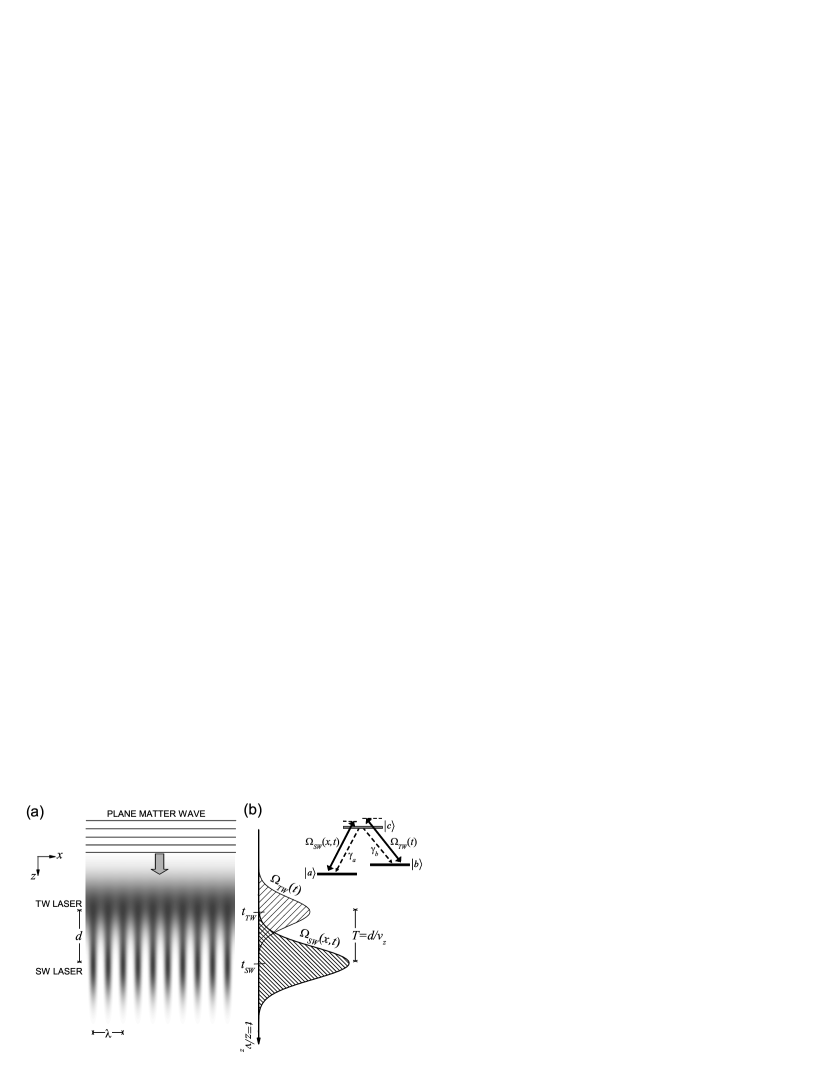
The schematics of the SLAP technique are shown in Fig. 1. A plane matter wave formed by three-level atoms in a -type configuration propagates at a velocity through two partially overlapping laser fields: the traveling wave (TW) couples the transition with a Rabi frequency and the SW couples the transition with a Rabi frequency . is the SW field wave number and the characteristic STIRAP time with the spatial separation between the centers of the two laser beams. () is the single-photon detuning between the TW (SW) field and the corresponding transition. () is the spontaneous emission decay rate from to (from to ). The spatial and the temporal variants of the SLAP technique are connected by the simple transformation .
Under the two-photon resonance condition , one of the position-dependent energy eigenstates of the -type three-level system is the so-called dark state where . STIRAP Ber98 consists in following this energy eigenstate from to smoothly changing from to by means of two partially overlapping laser fields as in the counterintuitive sequence of Fig. 1. To keep the system in the energy eigenstate, this process must be performed fulfilling the ’global’ adiabaticity condition Ber98 :
| (1) |
where is a dimensionless constant that for optimal Gaussian profiles and overlapping times takes values around 10 Kuk89 .
In the SLAP technique, we assume that the matter wave has been initially prepared, by means of e.g., optical pumping, into the internal state . Then, those atoms crossing the nodes of the SW remain in state while those interacting with the TW and the SW fields through the STIRAP process are transferred to state . Therefore, an intense SW field should produce sharp peaks on the spatial population distribution of state at its nodes. From Eq. (1) and assuming , the FWHM of these peaks is given by:
| (2) |
where with is the FWHM of the peaks in the Fabry-Perot type localization that would be attained by means of the CPT technique Aga06 . Therefore, for
| (3) |
the ’super-localization’ regime which we define by is reached. Note that for corresponding to optimal parameter values Kuk89 , condition (3) reads .
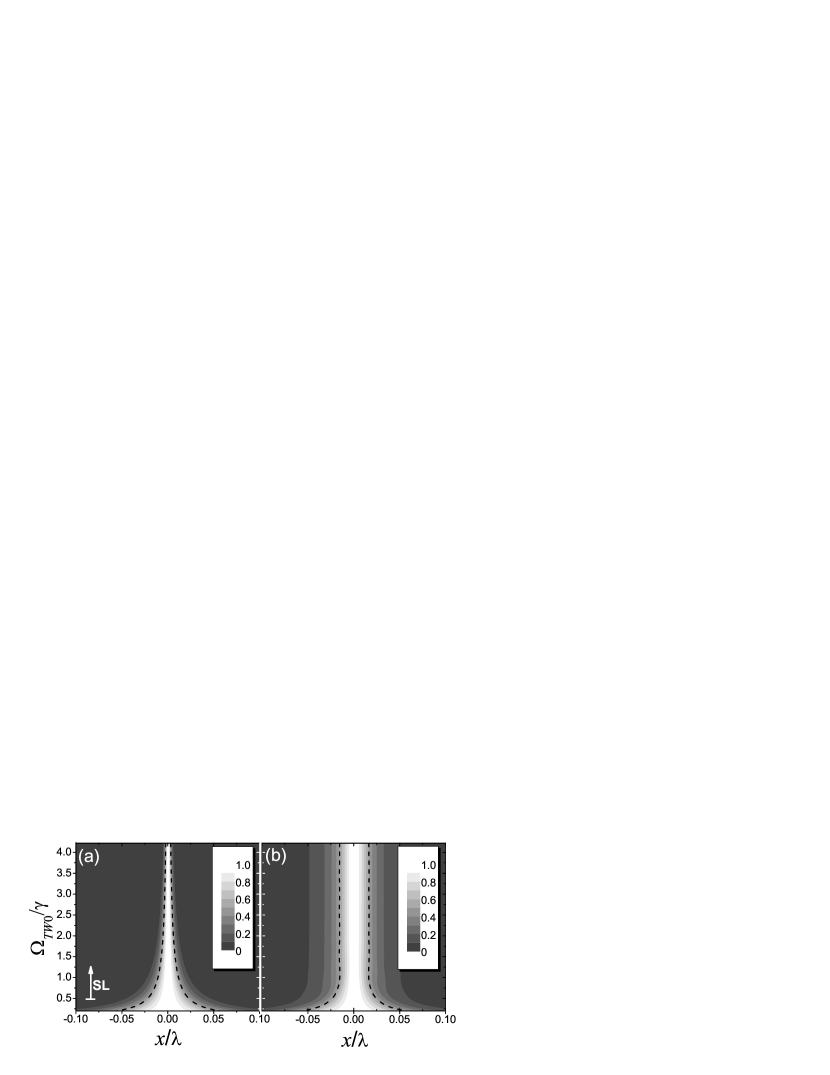
Fig. 2 shows numerical simulations of the state selective localization process by integrating the corresponding density matrix equations for both the SLAP and the CPT techniques. In the CPT technique Aga06 , subwavelength state-selective localization is obtained by reaching the steady-state through an optical-pumping process to the dark-state involving several cycles of laser excitation and spontaneous emission. In the setup of Fig. 1, the CPT process corresponds to , and , where we have assumed, for simplicity, . For and the rest of parameters given in the figure caption, Fig. 2(a) shows that for the super-localization condition (3) is fulfilled and the SLAP technique yields better localization than the CPT technique, i.e., .
Note that we have considered here, for simplicity, a 1D SW field in the - transition, although the SLAP techniques applies also to higher dimensions and to any arbitrarely spatially structured field presenting intensity nodes.
III SLAP based nano-lithography
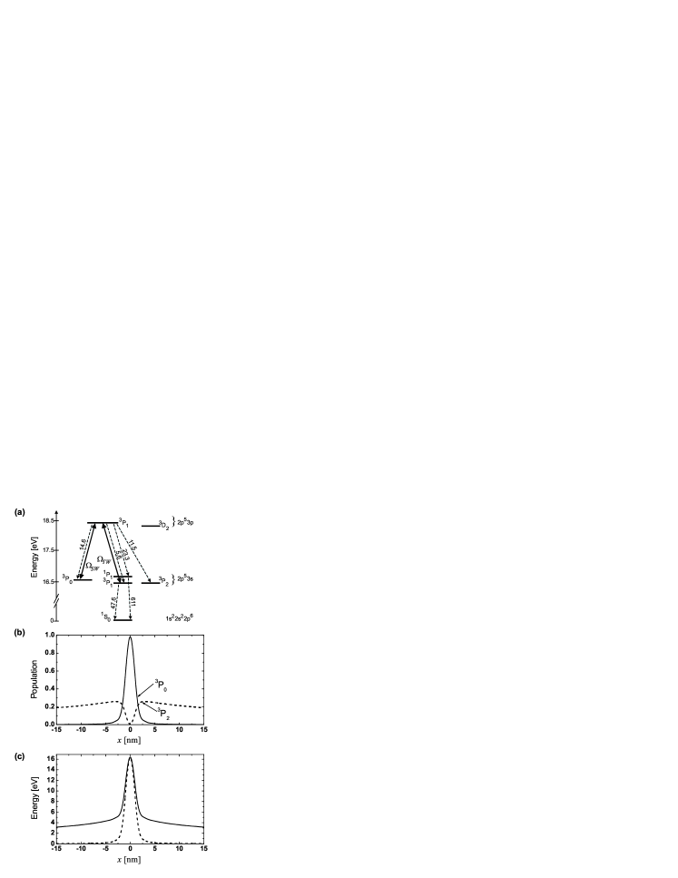
As a first implementation, we consider atom lithography based on substrates sensitive to the internal energy of metastable atoms ESL99 . For this purpose, we take a plane matter wave of metastable Ne* whose initial internal level has an energy of 16.6 eV and thus high potential for surface damage. In fact, Ne* is a prime candidate for coherent manipulation, since the STIRAP technique has been successfully reported with Ne* MSB96 using the scheme where the first and the last are long lived states (see Fig. 3(a)). However, here we are interested in applying the SLAP technique such that, away from the nodes of the SW, the initial state is adiabatically transferred to a fast decaying state in order to remove the corresponding high internal energy. Thus we consider the open three-level scheme (depicted in Fig. 3(a)) with state decaying to the ground state at a rate of . Fig. 3(b) shows subwavelength atom localization in state (solid curve) around a node of the SW (period of 308.2 nm) after the application of the SLAP technique for and the other parameters given in the figure caption. Note that although part of the population (dashed curve) is diabatically transferred to the high energy state with lifetime NeGerhard03 , this population could be efficiently pumped to the ground state via with an extra laser field. Thus, for realistic parameter values one would expect state selective localization with a FWHM of only a few yielding high contrast peak energies of 80% (solid curve in Fig. 3(c)) in the absence of depumping of the state, and of nearly 100% (dashed curve in Fig. 3(c)) in the presence of the depumping.
As an important feature of the SLAP technique, the localized state does not interact with the light fields at any time and therefore does not suffer from recoil induced broadening, which implies that the Raman-Nath approximation perfectly applies RNM01 . In this situation, the transversal velocity spread of the initial matter wave determines the ultimate resolution limit of the SLAP technique. Taking as the rms transversal velocity spread, the limit corresponds to . Thus, for typical parameters, , , and , localization down to single nm can be achieved. As given by the Heisenberg uncertainty principle, strong atom localization should also result in the appearance of high momentum components Aga06 . For the results shown in Fig. 3(b), we have verified that the highest momentum components do not have time enough to smear out the localized structure until the end of the SW where the substrate is placed.
IV Coherent patterning of a BEC based on SLAP
As a second implementation, we now focus on a trapped BEC of 87Rb to show the feasibility to generate narrow structures in the condensate by means of the SLAP technique. The -type three level configuration under study is depicted in Fig. 4. We consider a zero temperature two-species 87Rb BEC, and , confined in a one dimensional geometry. The description of the system is performed within the 1D coupled Gross-Pitaevskii equations:
| (4) | |||||
| (5) | |||||
| (6) | |||||
where the effective 1D nonlinearity is given by , with the interspecies () and intraspecies () -wave scattering lengths, and the transverse trapping frequency. In 87Rb the scattering lengths are known to be in the proportion with the average of the three being scattering . Since the magnetic moments of the two trapped components are the same to first order, magnetic trapping as well as optical trapping is possible with equal potentials for both components. The axial trapping potential reads , with the 87Rb mass and the axial trapping frequency. State is not trapped and the excited atoms are assumed to escape from the BEC at a rate .


To show the time evolution of the system during the SLAP process, we have numerically solved Eqs. (4)-(6) for a BEC of atoms. Figs. 5(a) and (b) show the mixing angle at one of the SW anti-nodes and the contour plot of the density distribution of atoms in state , respectively, as a function of time and for the parameters given in the figure caption. As expected, component develops extremely narrow structures at the nodes of the SW whose width is much smaller than its spatial period. For demonstration, we have chosen a large spatial period of 15 m but arbitrary periods down to with a corresponding localization down to the nm scale could be achieved by changing the wave number of the standing wave. Fig. 5(c) shows the time evolution of the FWHM around one node. The minimal width of the localized structures coincides approximately with the time at which the TW field is switched off, i.e., at . We have calculated the transverse momentum spread for this time, obtaining a beam quality factor ALas which is below the Heisenberg limit due to the non-linearities of the two-component trapped BEC partially compensating for diffraction.
V Conclusions and perspectives
In conclusion, we have introduced the SLAP technique for state-selective localization and patterning of atomic matter waves. We have shown that a ’super-localization’ regime beating the previously introduced CPT localization technique Aga06 can be reached and analytic expressions for the necessary conditions have been derived. We have discussed the use of the SLAP technique for nano-lithograhy with a Ne* matter wave showing the possibility to imprint high contrast patterns with narrow structures whose FWHM approaches the single nanometer scale. This lithographic technique is applicable to all atomic systems with a high-energy dark state formed by the combination of a state fast decaying to the ground and a metastable one. Coherent patterning of a two-component 87Rb BEC in the super-localization regime has been studied in detail as a second example showing that it is possible to overpass the Heisenberg limit.
Since localization occurs at the nodes of one of the involved laser fields, more evolved patterning schemes can be realized by extending the present 1D configuration to higher dimensions by applying 2D and 3D SW configurations. Even more complex structures, such as the intensity nodes of higher-order Laguerre-Gauss modes or the light fields of custom-made micro-optical elements Birkl01 , could be considered for this technique. Following the presented SLAP technique for coherent patterning of a BEC, one could consider its application to produce a collection of parallel, coherent, and extremely collimated (pulsed) atom lasers atomlaser or, by observing the corresponding near field diffraction pattern, to investigate the matter wave analogue of the optical Talbot effect Talboteffect . Finally, the SLAP technique could be also applied to address and detect individual sites in optical lattices by an appropriate choice between the spatial period of the optical lattice and the wavelength of the SW field used in this technique.
We acknowledge support by the Spanish Ministry of Education and Science under contracts FIS2005-01497, FIS2005-01369, FIS2008-02425, HA2005-0002, HD2008-0078, CSD2006-0001, by the Catalan Government under contract SGR2005-00358, by ESF and DFG under the project CIGMA, by the European Commission within the RTN Atom Chips and the IP SCALA, by the DAAD under contract 0804149, and by NIST under award 60NANB5D120.
References
- (1) For a review see: I. Bloch, Nature Physics 1, 23 (2005); M. Lewenstein et al., Advances in Physics 56 (2), 243 (2007); I. Bloch, J. Dalibard, W. Zwerger, Rev. Mod. Phys. 80, 885 (2008).
- (2) R. Scheunemann et al., Phys. Rev. A 62 051801(R) (2000); M. Saffman, Opt. Lett. 29, 1016 (2004); D. Schrader et al., Phys. Rev. Lett. 93, 150501 (2004); J. Cho, Phys. Rev. Lett. 99, 020502 (2007); M. Karski et al., Phys. Rev. Lett. 102, 053001 (2009); K. D. Nelson, X. Li and D. Weiss, Nature Phys. 3, 556 (2007).
- (3) K. Staliunas, S. Longhi, and G. J. de Valcarcel, Phys. Rev. Lett. 89, 210406 (2002); M. Modugno, C. Tozzo, and F. Dalfovo, Phys. Rev. A 74, 061601(R) (2006).
- (4) For a review on matter wave lithography see: C. A. Mack, Fundamental Principles of Optical Lithography: the Science of Microfabrication, (Chichester, West Sussex, England: Wiley, 2007); M. K. Oberthaler and T. Pfau, J. Phys.: Condens. Matter 15, R233 (2003); J. H. Thywissen and M. Prentiss, New Journal of Physics 7, 47 (2005); D. Meschede and H. Metcalf, J. Phys. D: Appl. Phys. 36, R17 (2003).
- (5) U. Drodofsky et al., Microelectron. Eng. 35, 285 (1997); R. E. Behringer et al., J. Vac. Sci. Technol. B 14, 4072(1996); Th. Schulze et al., Appl. Phys. B 70, 671 (2000).
- (6) R. Abfalterer et al., Phys. Rev. A 56, R4365 (1997); K. S. Johnson et al., Science 280, 1583 (1998).
- (7) P. R. Hemmer et al, Phys. Rev. Lett. 96, 163603 (2006); Q. Sun, P. R. Hemmer, and M. S. Zubairy, Phys. Rev. A 75, 065803 (2007).
- (8) M. Holland et al., Phys. Rev. Lett. 76, 3683 (1996).
- (9) E. Paspalakis and P. L. Knight, Phys. Rev. A 63, 065802 (2001).
- (10) M. Sahrai et al., Phys. Rev. A 72, 013820 (2005).
- (11) G. S. Agarwal, K. T. Kapale, J. Phys. B: At. Mol. Opt. Phys. 39, 3437 (2006).
- (12) M. Kiffner, J. Evers, and M. S. Zubairy, Phys. Rev. Lett. 100, 073602 (2008).
- (13) A. V. Gorshkov et al., Phys. Rev. Lett. 100, 093005 (2008).
- (14) S. E. Harris, Phys. Today 50, 36 (1997); E. Arimondo, in Progress in Optics edited by E. Wolf, Vol. XXXV, p. 257 (Elseveir Science, Amsterdam, 1996); M. O. Scully and M. S. Zubairy, Quantum Optics, Cambridge University Press, England, (1997); J. P. Marangos, J. Mod. Opt. 45, 471 (1998); J. Mompart and R. Corbalán, J. Opt. B 2, R7-R24 (2000); F. Silva et al., Phys. Rev. A 64, 033802 (2001).
- (15) H. Li et al., Phys. Rev. A 78, 013803 (2008).
- (16) K. Bergmann, H. Theuer, and B. W. Shore, Rev. Mod. Phys. 70, 1003 (1998).
- (17) J. R. Kuklinski et al., Phys. Rev. A 40, 6741-6744 (1989).
- (18) See Pierre Meystre, Atom Optics, Springer (2001) and reference therein.
- (19) A. Vardi et al., J. Chem. Phys. 107, 6166 (1997); P. S. Julienne et al., Phys. Rev. A 58, R797 (1998); M. Mackie, R. Kowalski and J. Javanainen, Phys. Rev. Lett. 84, 3803 (2000); J. J. Hope, M. K. Olsen, and L. I. Plimak, Phys. Rev. A 63, 043603 (2001); P. D. Drummond et al., Phys. Rev. A 65, 063619 (2002); H. Y. Ling, H. Pu and B. Seaman, Phys. Rev. Lett. 93, 250403 (2004); J. Cheng, S. Han and Y. J. Yan, Phys. Rev. A 73, 035601 (2006).
- (20) K. Winkler et al., Phys. Rev. Lett. 95, 063202 (2005).
- (21) K. C. Wright, L. S. Leslie and N. P. Bigelow, Phys. Rev. A 77, 041601(R) (2008).
- (22) P. Engels et al., Appl. Phys. B 69, 407-412 (1999).
- (23) J. Martin, B. W. Shore, and K. Bergmann, Phys. Rev. A 54, 1556 (1996).
- (24) M. Zinner et al., Phys. Rev. A 67, 010501(R) (2003).
- (25) J. M. Vogels et al., Phys. Rev. A 56, R1067 (1997); M. R. Matthews et al., Phys. Rev. Lett. 81, 243 (1998).
- (26) J.-F. Riou et al., Phys.Rev. Lett. 96, 070404 (2006); A. E. Siegman, IEEE J. Quantum Electron. 27, 1146 (1991); M. Jeppesen et al., Phys. Rev A 77, 063618 (2008); F. Impens, Phys. Rev. A 77, 013619 (2008).
- (27) G. Birkl et al., Opt. Comm. 191, 67 (2001); F. B. J. Buchkremer et al., Laser Physics 12, 736 (2002).
- (28) M. O. Mewes et al., Phys. Rev. Lett. 78, 582 (1997); H. M. Wiseman. Phys. Rev. A, 56 2068 (1997); B. P. Anderson and M. A. Kasevich, Science 282, 1686 (1998); I. Bloch, T. W. Hänsch and T. Esslinger, Phys. Rev. Lett. 82, 3008 (1999); E. W. Hagley et al., Science 283, 1706 (1999).
- (29) A. Turlapov, A. Tonyushkin, and T. Sleator, Phys. Rev. A 71, 043612 (2005).