1currently at ]Niels Bohr Institute, University of Copenhagen, 2100, Copenhagen, Denmark
Stimulated Raman process in a scattering medium in application to quantum memory scheme
Abstract
We consider the coherent stimulated Raman process developing in an optically dense disordered atomic medium, which can also incoherently scatter the light over all outward directions. The Raman process is discussed in context of a quantum memory scheme and we point out the difference in its physical nature from a similar but not identical protocol based on effect of electromagnetically induced transparency (EIT). We show that the Raman and EIT memory schemes do not compete but complement one another and each of them has certain advantages in the area of its applicability. We include in our consideration analysis of the transient processes associated with switching off/on the control pulse and follow how they modify the probe pulse dynamics on the retrieval stage of the memory protocol.
pacs:
03.67.Mn, 34.50.Rk, 34.80.Qb, 42.50.CtI Introduction
Quantum memories for light pose an extremely important problem for various protocols of quantum computing and secure communication BEZ ; Ralph ; Cerf , which might be solvable with currently existing technology. At present there have been several experimental demonstrations of storage and retrieval of non-classical states of light from macroscopic atomic systems KADHP ; HAAYANTFK ; AYANTFK ; JSFCP ; NGPSL ; CMJLKK ; EAMFZ ; COBPG ; CDLK ; HBGHABL . In many theoretical discussions the problem was tested in context of achievable fidelity for storage and retrieval of the original state of light, normally assumed either coherent, squeezed or single photon BEZ ; KMP ; Cerf ; Ralph ; SaBPtVL ; NWRSWWJ ; MKMP .
In the recently reported series of papers GALS thorough analysis was applied to determine the efficiency of storage and retrieval of a single mode quantum state of light via its lambda-type conversion into an atomic spin coherence. Such a conversion is normally associated with either electromagnetically induced transparency (EIT) two photon resonance, or with Raman process, or with photon echo effect. Optimization procedure and practical recommendations are often based on the unique properties of the lambda transition and presumes the quantum information encoded in collective variables of the light. For the weak coherent light (with small degeneracy parameter) this scheme describes, for example, the storage of a single photon quantum bit and relates the efficiency of the total pulse retrieval to the fidelity of the single photon quantum state retrieval. Such analysis is relevant for one mode memory channel and it leaves open important issues concerning storage and retrieval of a multimode quantum state. The quantum memory for the multimode configuration in the Raman process has been the subject of recent reports NWRSWWJ ; MKMP , which indicated the difficulties and necessity of additional studies.
In the present paper we shall discuss the stimulated Raman process in a scattering medium with a -type excitation, which is initiated by a control pulse of limited duration. We shall split this mechanism from the similar but not identical EIT two-photon resonance and discuss the difference between these processes. The Raman scattering in the Heisenberg formalism, introduced in Ref.RaymMost , and later applied to the quantum memory problem in Refs.KMP ; NWRSWWJ ; MKMP , is usually discussed for far frequency offsets of the probe and coupling modes from an atomic resonance and it is considered in approximation based on adiabatic elimination of the upper states. This approximation makes possible to build the relevant effective Hamiltonian and include the losses into the dissipation terms and the Langevin forces. In the present paper we show how the Raman process can be described for arbitrary frequency detunings and without such a simplifying approximation. We show how the Raman process can be discriminated from the EIT two-photon resonance for any frequency detunings via considering the spectral behavior of the sample susceptibility dressed by the coupling field.
Our analysis aims to clarify the physical requirements, for dependable manipulation with the light pulse and atomic coherence at each step of the complete memory protocol. The important physical processes like atomic motion and transient effects associated with switching off/on the control pulse will be described. In the last part of the paper we briefly comment how our approach can be generalized to a multilevel configuration while paying attention to the hyperfine structure of alkali atoms, which was earlier considered in a lossless configuration in Ref.MKMP . As an important consequence of our analysis we shall point out that the EIT resonance and the Raman process are not competitive protocols but actually complement one another. The protocol based on the EIT effect works better for pulses longer than the natural atomic lifetime , but the Raman protocol is in principle applicable for pulses with duration around . Thus the Raman scheme can potentially work for pulses around 20 ns and hence extend the range of pulses, which could be stored in the atomic spin subsystem. That would lead us to wider demonstrations of atomic memory for unknown states of light arriving from radiation sources of different physical nature.
The paper is organized as follows. In section II we describe our approach to the stimulated Raman process, which is based on the Green’s function formalism. We indicate some technical advantages in applying diagram analysis particularly to the atomic memory problem. In section III we make a diagram derivation of the master equation describing the dynamics of the probe pulse and atomic coherence on the write-in and retrieval steps of the memory protocol. Our general discussion is further illustrated by numerical simulations for the Raman process given in section IV. Some details concerning the Green’s function formalism are presented in appendix A.
II Basic assumptions and calculation approach
Transport of a light pulse in a medium under conditions, where the coherent forward propagation is damped by losses due to incoherent scattering over all outward directions, is a quite delicate problem to describe theoretically at the quantum level. The problem becomes even more subtle for practically important situation when the energy of the transmitted pulse is comparable with the scattered light energy. If the losses are significant and the light and atomic subsystems are initially prepared in arbitrary quantum states it would be difficult to follow the dynamics of the entire atoms-field subsystem completely in a three dimensional configuration, see SornsSorns . An essential simplification can be achieved if the light and atomic subsystems are initially in a coherent state and the interaction process does not modify this type of state Coherence . Such a dynamical process, which reproduces most of the principle features of the quantum memory protocol, we shall discuss in this section.
II.1 Description of the light subsystem
For a coherent state any quantum characteristics of light can be defined in terms of the complex amplitude of the electric field given by the expectation value of its Heisenberg operator considered at the certain spatial point , time and averaged over the asymptotic state of the system in the infinite past
| (1) |
Here and are the positive frequency parts of the -th polarization component of the electric field operators in the Heisenberg and interaction representations respectively, which are related by the following unitary transform
| (2) |
where is the interaction Hamiltonian in interaction representation, see Eq.(6) below, is the time-ordering operator, and the S-matrix in expression (1) is given by principle limit of the evolutionary operator .
If the light pulse crosses the medium in a single pass, its forward propagation obeys the mesoscopically averaged Maxwell equation, which can be constituted and solved under rather general assumptions. The field emerging from the sample via incoherent scattering can be visualized as secondary waves created by a disordered system of atomic sources. For the weak field, scattered by the sample, its intensity, angular and spectral distribution can be found by analysis of the multiple scattering process. To entirely simulate this process the Monte-Carlo scheme can be applied.
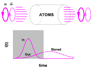
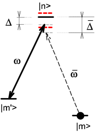
Let us make these general statements more concrete in context of the -configured transition, shown in figures 1 and 2. The depicted scheme is routinely discussed as theoretical background for description of the stimulated Raman process or EIT two-photon resonance. A strong coupling field with right-hand circular polarization is quasi-resonantly applied between a Zeeman hyperfine sublevel of the ground state and a hyperfine component of the excited level near the upper Zeeman state . A weak probe beam is also quasi-resonant with the Zeeman hyperfine transition. All nonlinear optical effects associated with the probe light are assumed to be negligible. In our discussion this field will be taken into account only in the first non-vanishing order. The atomic medium consists of the atoms initially (in the infinite past) populating state , such that the presence of the weak probe initiates only weak transfer of atoms from state to . The sample is optically dense for the probe field and fully transparent for the coupling field.
Both the coupling and the probe fields are in a coherent state and completely characterized by the complex amplitude (1) projected onto the relevant polarization and/or spectral states that makes these modes distinguishable. The properties of the coupling field are not modified at all because the sample is transparent and the number of photons coherently scattered into the coupling mode is negligible in comparison with the quantum uncertainty of the number of photons contributing to this mode. Thus the evaluation of the expectation value (1) based on a relevant diagram expansion need to be performed only for the probe field. This calculation will automatically include all the dressing effects associated with the coupling field and describe in one formalism two different physical phenomena: stimulated coherent Raman process and EIT two-photon resonance. The difference between these phenomena will be further clarified by considering different physical limits and spectral relations attaining the delay effect and minimizing the incoherent losses.
The global advantage of the coherent state in comparison with other more sophisticated quantum states, such as squeezed, entangled etc., is a relatively simple diagram analysis for the expectation value of the field amplitude (1). Its expansion in the series of perturbation theory under application of Wick’s theorem transforms any outcoming product of the field operators to -ordered form, and generate only the simplest diagram objects such as the non-perturbed coherent amplitudes of incoming field and the vacuum-type Green’s functions. This makes it technically possible to further describe the probe field dynamics in terms of mesoscopically averaged Maxwell equations and multiple scattering light diffusion.
II.2 The atomic subsystem and interaction process
We consider the macroscopic atomic system in the second quantized formalism. In this subsection we shall show that for an atomic ensemble underwent coherent-type interaction process shown in figures 1 and 2 the quantum dynamics can be properly described by the following four Green’s functions of the Perel-Keldysh diagram technique Keldysh ; LaLfX ; BKS
| (3) |
These Green’s functions with give the expectation values of the different products of creation and annihilation -operators ordered by chronological operators . The permutation operators realize the following action: arranges the -operators as ordered in time, its counterpart arranges them as anti-ordered in time, operators and are respectively identity and transposition operators.
The -operators responsible for anihilation or creation of an atom at spatial point and in internal state can be expanded in the basis set of plane waves as follows
| (4) |
where is the quantization volume, and and are respectively the operators of annihilation or creation of an atom with momentum in internal state in the Heisenberg picture.
If the atomic motion has semiclassical description then the Green’s function before interaction can be conveniently expressed by the single particle density matrix in the Wigner representation
| (5) | |||||
where the external sign or corresponds to bosonic or fermionic statistics of atoms. In this integral relation the exponential factors are responsible for free dynamics of the atomic state and show fast oscillation in space and time. The Wigner density matrix is also oscillating in time with the frequency such that the integrand itself has free precession as function of times and with internal energies and respectively. The validity of expression (5) is constrained by the requirement that the atomic de-Broglie wavelength , where ”” is atomic mass and is ensemble temperature, should be much less than the scale of spatial inhomogeneity. Then the approximation of the true Green’s function by expression (5) is applicable if variations of the increments and are small in comparison with the spatial and time scales where the Wigner function is significantly changed. For free dynamics and without spin relaxation process the density matrix of the ground state can only be modified because of atomic motion in free space or in a trap.
It is important to recognize that without interaction with the light subsystem the Wigner density matrix gives a complete description of the macroscopic atomic subsystem. Indeed, as one can verify each of the remaining Green’s functions (3) can be expressed by integral relations similar to expression (5), see LaLfX ; BKS for details. The additional terms, which distinguish the four Green’s functions, given by Eq.(3), are expressed by the commutator (for fermion case by the anti-commutator) of the free Heisenberg -operators. These terms contribute to with additional multiplication by to (retarded type) and by to (advanced type). In turn each commutator (or anti-commutator) can be expressed by a similar expansions in the momentum representation and described by similar exponential functions of and as in Eq.(5) if the atomic motion is free. For a coherent initial state of the atomic system, when all the atoms occupy only one Zeeman state, any correlation function of higher order can be expressed as a product of the lower order Green’s functions defined by Eq.(3).
The coherent type interaction process shown in figure 2 is driven by the following interaction Hamiltonian
| (6) | |||||
where all the time dependent operators are written in the interaction representation as indicated by the zero subscript and denotes the matrix element of the -th component of an atomic dipole. The second line constitutes the rotating wave approximation and convert to algebraic form the normal differential relation between the transverse vector potential operator and the electric field operator . This presumes that both the frequencies of the coupling field and the probe field are indistinguishable from an average frequency for the atomic optical transitions shown in figure 2.
As one can verify via perturbation theory to lowest order the probe field, the interaction process shown in figure 2 will not break the Gaussian factorization for any higher order correlation functions. This means that the interaction process leaves the atomic system in the state described by a single particle density matrix. Any atomic correlation function is described by the retarded or advanced type Green’s functions dressed by interaction with the strong field. As we shall further show the main optical characteristics of the sample are expressed by such a dressed retarded Green’s function of the excited state. This Green’s function can be found in analytical form for a control pulse of arbitrary duration and in quite general assumptions, see appendix A. The propagation of the probe pulse through the medium can be visualized as a polaritonic wave, both for the stimulated Raman and the EIT processes.
III Dynamics of the probe field and atoms for -type excitation in the optically thick sample
III.1 Write-in stage of the memory protocol
The dynamics of the entire system consisting of the probe field and atoms can be described via diagram analysis of the atomic and field Green’s functions introduced in the previous section. After a certain regrouping of partial contributions generated by the expansion of perturbation theory for the evolutionary operator one obtains the following Dyson equation for the probe field amplitude
|
|
(7) |
Here the double wavy single ended lines describe the probe field amplitude dressed by the coherent interaction shown in figure 2. The single double ended wavy line is the causal (retarded in the RWA approach) Green’s function for light propagating freely in vacuum. The loop consisted of the atomic Green’s functions and the vertices describe the polarization operator or susceptibility of the sample in response to the probe field. The equation (7) graphically represents the macroscopic Maxwell equation. More detailed analytical description of the atomic Green’s functions is specified in appendix A.
The dynamics of the atomic coherence can be identified if the solution of equation (7) is known. This requires evaluation of the following diagram for the Green’s function defined by Eq.(3) and created by the interaction process
|
|
(8) |
Here the internal doubly line represent the retarded type Green’s function of an excited atomic state dressed by the interaction with the vacuum and coupling modes, see appendix A. The outward directed dashed arrow represents the field amplitude of the coupling mode. The thin lines are related to the non-perturbed dynamics of free atoms in the ground state and are given by semiclassical approximation (5).
The strategic idea of the write-in step of the memory protocol is that equation (7) should generate probe pulse delayed so much as it practically does not emerge from the sample during the action of the control pulse. At the same time the probe light should not be incoherently scattered by the sample and after the interaction the information, originally encoded in the probe pulse, will be concentrated in the spin subsystem. The dynamics of the probe field in this process is driven by equation (7), which has the following analytical form
| (9) |
where is the slow-varying amplitude of the probe mode, which is given by a factorization of the probe field component defined by Eq.(1)
| (10) |
The Maxwell equation (9) indicates that in a dilute sample the coherent part of the probe pulse propagates only forward and the profile of the outgoing pulse strongly depends on properties of the sample susceptibility , which controls the efficiency of the memory protocol. The diffraction divergence was completely ignored in the derivation of Eq.(9) and was treated only as a parameter.
Since the coherent process shown in figure 2 does not disturb the original equilibrium distribution of atoms, the ground state density matrix can be factorized as
| (11) |
where is the equilibrium Maxwell distribution of the atomic momenta. In the case of an isolated single -type excitation the diagram expression (8) leads to the following kinetic equation for the off-diagonal ground state matrix elements of the atomic density matrix
| (12) | |||||
where the scaling factor
| (13) |
is responsible for the difference in the interaction vertices contributing to the polarization and self-energy operators of the diagrams (7) and (8) respectively. Here is the transition matrix element for interaction with the strong coupling field, and , are the Zeeman states coupled by the interaction process. Vectors and are respectively unit polarization vectors for right-handed and left-handed polarizations. The strong mode is assumed to be described by the following positive frequency component
| (14) |
i. e. to be nearly monochromatic during the action of the control pulse with the envelope profile .
Both equations (9) and (12) are described by the same sample susceptibility. The hardest obstacle for further application of equation (9) is that the susceptibility is not known analytically in the general case, when atoms have a multilevel energy structure and the control pulse have an arbitrary envelope profile. It can be described analytically only after a round of approximations with respect to the dressing effects associated with the coupling field and the internal atomic interaction. In appendix A we calculate it for the case of rectangular profile, when the control pulse has duration
| (15) |
where is the step function. For this particular case the Maxwell equation (9) can be solved numerically. Then the distribution of the spin coherence in space and in time can be found via straightforward integration of equation (12).
Together the equations (9) and (12) describe transport of a spin polariton mode through the atomic sample, which dynamics can be approximated by either EIT-type FleischhLuk or Raman-type RaymMost . As was mentioned above, the strategic line of the write-in step of the memory protocol is to stop the control pulse at a time, when the probe mode has not emerged from the sample and the polariton is localized at least on the scale of the sample. Then after a round of transient processes the state of the light will be mapped onto spatially extended state of the atomic spins in the sample. Without any external disturbances this state will be preserved and will store the mapped quantum state of the probe light.
In ideal situation this process does not add extra noise to the state. The crucial requirement to make the memory protocol feasible, as it was discussed in Refs.FIM ; NWRSWWJ ; GALS , is that the sample should have extremely high optical thickness, such that , where is a density of atoms, is a wavelength divided by for either probe or coupling mode, and is the sample length. If this requirement is fulfilled, which is principally important for both the Raman and EIT memory schemes, the delay time for the transport of the probe pulse through the sample can be made longer than the input pulse duration and the spin polariton can be localized in the sample.
III.2 Retrieval stage of the memory protocol
If the coupling light is switched off and after a controllable delay switched on again, the probe pulse can be stored and retrieved. The delay time is mainly limited by relaxation processes for the spin coherence. In the case of cold atoms the spin relaxation can be minimized but atoms can leave the interaction area because of free motion while the confining trap fields are switched off during the entire protocol time. However for delay up to few milliseconds the atoms can be considered as non-drifting and the retrieval stage can be initiated by recovering the polariton dynamics with the second coherent pulse.
The probe field dynamics is now described by the following Dyson equation
|
|
(16) |
The first term on the right hand side displays the source for the optical coherence initiated by the second control pulse. The black wavy line performs here electric field of the incoming probe pulse, i. e. the solution of equation (7). Since the probe pulse has arrived with the write-in control pulse the right vertex of this term relates to times associated with the write-in stage of the protocol. But the left vertex relates to times belonging the readout control pulse.
The broken double line denotes the retarded Green’s function of the excited atomic state dressed by both the write-in and readout control pulses and has the following diagram definition
|
|
(17) |
The incoming double line is the excited state Green’s function dressed by the write-in control pulse. The outgoing double line is the excited state Green’s function dressed by the readout control pulse. These two lines are converted into the ground state vacuum line at the vertex points associated with the coupling fields for write-in (W) or readout (R) control pulses. Just because the vacuum dynamics, described by the thin solid line, preserves the atomic state for infinitely long time this diagram being inserted into equation (16) can be visualized as the spin coherence, which was originally created by the process (8), and which now regenerates the weak probe field via a stimulated Raman process when the readout control pulse is applied.
The second term in equation (16) is similar to the second term in equation (7) and is responsible for the Maxwell dynamics of the recovered probe field. The red dashed wavy line reproduces the recovered probe field for which this equation actually should be solved. In analytical form the diagram equation (16) can be written as follows
| (18) | |||||
where is the solution of Eq.(9) and is field amplitude of the recovered pulse, for which equation (18) should be solved. It is assumed that at the beginning of the readout control pulse the incoming probe pulse is over. Despite the lower limits of the integrals in the right hand side are in infinite past, in reality the integrands are non-vanishing only if belongs the writing control pulse in the first integral and the readout pulse in the second. The susceptibilities and are given in appendix A in example of an isolated -type transition.
The dynamics of atomic coherence is now described by the following diagram equation
|
|
(19) |
which in turn leads to the following kinetic equation for the density matrix (11)
| (20) | |||||
Similar comments to those given for (18) above apply to this equation, which is responsible for atomic dynamics at the retrieval stage. In application it is only necessary to solve equations (9) and (18), and then can be found by straightforward integration of (20). In practice it is even not so important to know the solution for remaining atomic coherence because all the retrieved information goes out with the recovered probe pulse and the equation (20) should lead to a trivial result in the infinite future . However we introduce this equation for completeness of the description of the memory protocol.
IV Results and discussion
IV.1 The EIT effect and Raman process
Let us briefly discuss the difference between these two physical mechanisms when the propagation of the probe field is controlled by a stationary coupling field. Referring to the definitions of figure 2 one can define the following frequency detunings for the coupling mode and for the probe mode from the atomic transition frequencies and respectively. Then one can select two important resonance relations between the carrier frequency of the probe mode and the energy spectrum of the ”dressed” atom. The resonance point defines the two photon resonance, which is associated with EIT. Indeed the propagation function of the atomic excited state (25) as well as the sample susceptibility (35) vanish at this point for a pure monochromatic -type interaction of the modes and . The sample becomes transparent and any spectrally narrow probe pulse distributed in the vicinity of this point will cross the sample with extremely low group velocity. The light delay, associated with the EIT effect, does not principally depend on frequency offset and, in particular, the group velocity near the EIT point depends only on relation between the Rabi frequency of the coupling mode, atomic density and and not on , see Ref.FIM . For a sample with high optical depth, such that , and for any the probe pulse characteristics can always be adjusted to realize its slow transport or storage in the sample.
Another resonance situation takes place if the carrier frequency of the probe pulse is scanned near the frequency shifted quasi-energy component of the Autler-Townes doublet as shown in figure 2. This resonance point manifests itself as a narrow high amplitude spectral feature in the behavior of the dispersion and absorption components of the sample susceptibility, see Ref.FIM . In the Maxwell equation (9) the spectral overlap of the probe pulse with the dispersion part of the Autler-Townes resonance is responsible for lossless coherent forward propagation, which is normally associated with the stimulated Raman process. The overlap with the absorption part generates the incoherent losses caused by quantum radiation coupling of such an exciton-type atomic state with the continuum of vacuum modes.
As can be verified in the limit when the Rabi frequency is much less than detuning , the equations (9) and (12) can be transformed to the system of equations introduced in Ref.RaymMost and discussed later in the context of quantum memory in Refs.KMP ; NWRSWWJ ; MKMP . This transformation is equivalent to the standard procedure of adiabatic elimination of the optical atomic coherence, which was a basic assumption of the above papers. But we can point out that such an approximation is only valid if in the integrand in Eq.(9) the carrier frequency of the probe mode is located near the Autler-Townes resonance peak, which always requires for large some overlap of the pulse spectrum with this resonance. The importance of this overlap for the problem of optimization the probe pulse storage was earlier commented in Ref.GALS and in particular we address the reader to the second paper of that series. It is also important that in the coherent stimulated Raman process the photons of the probe mode transform to the coupling mode in result of interaction with all atoms of the ensemble. After a certain delay the photons of the probe mode are recovered via reversing interaction of atomic coherence with the coupling field. The Raman mechanism would exist even if the strong coupling field were exactly on resonance with the atomic transition, i. e. for when the problem becomes symmetric with respect to both components of the Autler-Townes doublet. We demonstrate this possibility by results of our numerical simulations given below.
Applying the Raman process at any the spontaneous losses can be always minimized by appropriate adjustment of the external parameters and by optimization of the pulse shapes, see Refs.GALS ; NWRSWWJ . This normally assumes either optimization of the probe pulse parameters with respect to a given shape and the frequency detuning of the control pulse or alternatively the optimization of the control pulse with respect to a given probe pulse. In an idealized lossless situation the stimulated Raman process could be considered as evolving purely dynamically. But because of the losses the efficiency of the coherent forward scattering is not responsibly high. In contrast to the EIT transparency point, for the Raman situation the forward coherent scattering is more sensitive to the frequency offset because the spectral behavior of the sample susceptibility near the Autler-Townes resonances is essentially modified with varying . Still at a given detuning and high optical depth the parameters of the probe pulse can be adjusted for its optimal storage.
Both the Raman and EIT mechanisms for delay of the probe pulse are generally applicable for any detuning of the coupling mode from the atomic resonance. As commented above, in a stationary situation, both are described by the spectral behavior of the same sample susceptibility but considered in different spectral domains. For general relation among external parameters these spectral domains can be only conventionally discriminated. However in many practical realizations the EIT zone and the Raman zone can be clear separated. It is important to recognize that for both the processes the crucial feature is the spectral behavior of the dispersion part of the sample susceptibility. It can be steep either near the transparency point (EIT) or near the absorption point of the Autler-Townes resonance (Raman).
The delay effect attains by the spectral overlap of the pulse spectrum with the sample susceptibility near any of these points. For the EIT scheme it is preferable to keep the pulse spectrum closer to transparency window and the protocol would work better for longer pulses (in scale of natural lifetime) and for smaller Rabi frequencies of the coupling field. For Raman scheme the pulse spectrum should be concentrated close but outward from the absorption peak. Thus the Raman protocol can be designed for large Rabi frequencies and for shorter pulses, which duration can be comparable with atomic natural lifetime. Rigorously speaking the EIT scheme can be also applied for storing of the short pulses if the Rabi frequency is large such that . But in this case the slope of the dispersion curve at the EIT point is always less steep than in vicinity of the Autler-Townes resonance. Thus the delay effect would manifest itself more effectively for the pulse which spectrum is located closer to the Autler-Townes resonance point.
IV.2 Dynamics of the probe pulse under the Raman process
The general formalism developed in the previous section can be illustrated by the propagation of a probe pulse with a Gaussian intensity profile
| (21) | |||||
where for the sake of convenience we rescaled the field amplitude to unit ”pulse energy”. The input field amplitude has the following Fourier component
| (22) |
The time shift can either be associated with the central point of the control pulse or, in a general situation, just defines the time of the probe pulse arrival. The time or spectral extension of the pulse profile is described by its spectral variance .
As an illustrative example of the -configured transition we consider the Zeeman states in the hyperfine manifold of cesium atoms. As an initial coherent state, which can be prepared by optical pumping repopulation processes, we consider the central Zeeman state of the lower (ground) hyperfine sublevel , which is a typical situation for experiments with cesium atomic clocks. The upper state , see figure 2, we will associate with the relevant Zeeman state of the lower hyperfine sublevel in the excited state of the -line, such that . The state , coherently coupled to , is the relevant Zeeman state of the upper (ground) hyperfine sublevel, such that for cesium . This convention in selection of atomic transitions lets us define the scaling factor (13), but all the qualitative results, discussed below, will be generally valid for any -scheme. We can also point out that the considered configuration of atomic transitions is well approximated by -scheme up to detunings more than hundred , since the nearest hyperfine sublevel in the upper state is separated by .
In figure 3 we show how the spectral profile overlaps with the real and imaginary parts of the susceptibility spectral component when the atoms are dressed by a stationary monochromatic coupling field. The overlap of the pulse spectrum with the sample susceptibility can be controlled by mismatching the carrier frequencies/detunings of the coupling and probe modes , see figure 2. The origin of the plot in figure 3 indicates the location of the EIT point and for the given spectra the probe pulses do not overlap at this point.
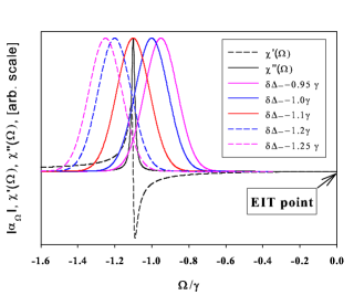
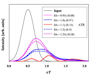
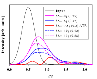
Variation of the spectral location of the probe pulse near the Autler-Townes resonance leads to different overlaps with the real and imaginary parts of the sample susceptibility. As a consequence, the influence of absorption (incoherent scattering) and delay effects on the pulse propagation will be also different with variation of . The negative role of absorption essentially falls off with deviation of from the exact resonance point (red curve in figure 3), but the positive tendency associated with pulse delay can survive. This is illustrated in figure 4 by tracking the time dependence of the outgoing pulses, which had the same initial spectral characteristics as in figure 3 and passed through the optically thick sample with . As follows from the plotted dependencies, when absorption is more or less negligible and the transmittance efficiency is around 70%, the pulse delay is still a perceptible effect. Let us point out that this predicted transmittance efficiency for delayed pulse is a certain indicator that the Raman protocol in the discussed conditions, coordinated with the currently existing experimental capabilities, can be applied, for example, for quantum storage of a single photon state with unknown polarization CDLK . In this situation it overcomes the best classical estimate ”2/3” , see Ref.MasPop for detail. It is also noteworthy that in the perfect resonance situation the outgoing pulse splits into a double-bell spectral profile, which in turn leads to oscillating time dependence of intensity, see figure 4.
IV.3 The pulse storage and retrieval
In figure 5 we demonstrate the complete memory protocol, when the coupling light is switched off and switched on again after a controllable delay. The input pulse characteristics and the sample depth are given by the same values as in figures 3 and 4. From the plotted graphs it is evident that after a round of fast transient processes (poorly resolved in time scale of these graphs) the retrieved parts of the pulses perfectly reproduce the delayed parts of the original pulses. This can be seen by direct comparison with figure 4. The transient oscillations have a frequency around and a relaxation rate around , such that they extend on very short time compared with the pulse duration. For storing such a long pulse, in the considered configuration, the efficiency around is achievable for effective overlap with the dispersion part of the sample susceptibility, see figure 3.
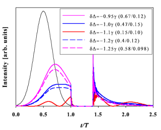
Let us consider now how the Raman protocol can be designed for storing shorter pulses with duration comparable to the atomic natural lifetime. In figure 6 we show the time dependence for a set of output probe pulses, when the coupling field is applied exactly at resonance to the atomic transition, such that . In this case the spectral widths of both components of the Autler-Townes doublet are around the natural decay rate and the Raman scheme can be applicable for delay of short probe pulses. For the graphs plotted in figure 6 the arrival time is given by and for the duration of the pulse, described by the time profile (21), is approximately the same as the atomic natural lifetime. Other relations and parameters are specified the same as for the graphs of figures 3 and 4. As a consequence the time dependence for the transmitted pulses, shown in figure 6, for varied mismatching of their carrier frequencies from the reference frequency of the coupling mode, look qualitatively similar to the relevant time dependence shown in figure 4. However the quantitative difference is great since the pulse duration and delay time are much shorter in the case of figure 6. The qualitative similarity in propagation of long and short pulses under stimulated Raman protocol is explained by the similarity of the absorption/dispersion spectral profile of the Autler-Townes resonance for (fig.4) and for , (fig.6).
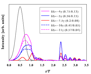
The situation changes dramatically if we look at the complete memory protocol applied to short pulses, see figure 7. As seen from this graph the role of transient processes becomes much more important in this case. There are evident manifestations of strong Rabi oscillations after switching off the control pulse as well as after switching it on again. These Rabi oscillations are damped on a time scale associated with the atomic natural lifetime. This time scale coincides with the pulse duration itself, such that the Rabi oscillations always accompany the retrieval step of the memory protocol under the described conditions. Let us point out that the calculations presented in figure 7 were done for a realistic value of the atomic optical depth and are feasible for experimental verification.
V Conclusion
The presented results and our discussion did not pursue the precise optimization of the pulse characteristics for efficient retrieval. But we can make some general observations, concerning the applicability of the quantum memory protocol. Depending on the type of the memory protocol it may be or may not be sensitive to the frequency detuning of the coupling mode from the unperturbed atomic resonance transition. For the EIT regime and in pure configuration the probe light group velocity is not sensitive to the location of the transparency point. If the on-resonance optical depth of the sample is large enough the same integral efficiency for the probe pulse storage and retrieval can be probably achieved at any detuning by proper adjustment of the original pulse parameters. In free space configuration the probe pulse stored under EIT protocol should preferably have duration much longer than the atomic natural lifetime.
In contrast for the Raman protocol the pulse dynamics is differently described under resonance and non-resonance conditions. An important consequence of our analysis is that the Raman protocol can be applicable for storing the pulses with duration comparable to the atomic natural lifetime. The main experimental difficulty in achieving the natural lifetime limit is the large magnitude of the Rabi frequency of the coupling field, which in such a case would be hard to stabilize. As we have pointed out and supported by our numerical simulations presented in section IV, the EIT and Raman protocols do not compete but actually complement one another. Each protocol has certain advantages in the area of its applicability. From the practical point of view for both the protocols the retrieval efficiency is expected to be high enough for sample with on-resonance optical depth around hundreds and at such depths would be quite tolerant to the variation of the probe pulse shape.
We have also considered the manifestation of transient processes associated with switching off/on the control pulse. As shown by our numerical simulations the storage of short coherent pulses via the Raman protocol is accompanied by Rabi-type modulations of the retrieved pulse. The decay time of the Rabi-type oscillations and the pulse duration have approximately the same order of magnitude in this case. In the context of the memory protocol this is not a noteworthy effect when the coherent probe pulse approaches the single photon state and the encoded quantum information is associated with the polarization degrees of freedom of the probe light, see Ref.CDLK . But the effect becomes very important for continuous variable schemes because it essentially modifies the spectral properties of the probe light as a carrier of quantum information. In this sense we point out that undesirable manifestation of the transient processes is usually less important for pulses, with duration much longer than the atomic natural lifetime. If storage and retrieval of such long pulses is controlled by the coupling field applied in the wing of the atomic resonance line, then the modulation frequency of the Rabi-type oscillations is increased and the degradation of the transient processes has much shorter time extension than the pulse duration itself.
The above recommendations are quite general and are not constrained by unique properties of the -scheme. Let us briefly comment how the developed approach can be further generalized to the situation of real alkali atom with attention payed to the hyperfine structure in the upper state. It is important to take into consideration the hyperfine effects when probing the system in the wings of either the or lines. For the coupling field tuned exactly in atomic resonance or detuned from it by a distance of few the -type approximation seems quite realistic and our results are applicable. For the practically important situation when the Rabi frequency is expected to be much less than the hyperfine splitting () and in the case of far detuning it is natural to expect a generalization of the Heisenberg approach introduced in Ref.MKMP by adding the scattering terms and the respective Langevin forces in. The important point for including the losses is that the incoherent scattering should be considered not only from the atom-associated components of the Autler-Townes structure (which in the limit reproduce the atomic resonances) but also from the field-associated component (which in the same limit is located near the field mode), see figure 2. It is expected that the field-associated component will be significantly modified due to effects of hyperfine interaction.
Acknowledgments
We thank Prof. E.S. Polzik for fruitful discussions. The work was supported by INTAS (project ID: 7904) and by RFBR (project # 08-02-91355). O.S.M. and A.S.S. would like to acknowledge the financial support from the charity Foundation ”Dynasty”. O.S.M. would also like to acknowledge financial support from the President Foundation of Russian Federation.
Appendix A The atomic Green’s functions and sample susceptibility
A.1 Monochromatic coupling field
The retarded-type Green’s function of the excited atomic state dressed by interaction with the vacuum modes is expressed by the standard Dyson equation
|
|
(23) |
and then interaction with the coupling field modifies it to the following form
|
|
(24) |
The thin solid and wavy lines are respectively non-perturbed vacuum Green’s functions of the atom and field. Other notation is explained in the main text of the paper.
For excitation of the atom by a monochromatic coupling mode these equations can be solved by Fourier transformation. In the reciprocal space one has
| (25) |
Here and are respectively the wave vector and frequency of the coupling mode and denominator is expressed by the two resonance components of the Autler-Townes doublet
| (26) | |||||
where is the transition frequency and is the rate of natural decay of the upper state. Applying the reverse Fourier transform over the ”energy” argument one arrives to the following Green’s function, defined in the mixed time and momentum representation
| (27) | |||||
The reverse Fourier transform from momentum to spatial coordinates
| (28) |
cannot be evaluated analytically in the general case. However when considering ultracold atoms with temperature significantly lower than the Doppler limit the effect of atomic motion is rather weak and can be taken into account as a small correction to the approximation of stationary atoms. For the Raman process, when the frequency detuning between the coupling mode and atomic frequency is large enough, the effect of atomic motion becomes even less important in the calculation of the sample susceptibility. But it gives the principle limitation for the storage time of the memory protocol as discussed in subsection III.2 and commented below in sec. A.4.
A.2 Coupling with a rectangular time envelope profile
If the action of the coupling mode is limited in time and described by a rectangular envelope profile (15) inside the interval , then the Green’s function defined in the mixed representation for different relations between times and is given by
1.1) and
| (29) |
1.2) and
| (30) | |||||
1.3) and
| (31) | |||||
2.1) and
| (32) | |||||
2.2) and
| (33) | |||||
3) and
| (34) |
These expressions for the Green’s function in different time domains can be built up by clipping the partial solutions for different excitation regimes. These include the atomic dynamics driven by either interaction only with the vacuum modes (29), (34) or jointly with the vacuum and coupling modes (27). The required boundary conditions are dictated by continuity at the points .
A.3 Susceptibility of the sample in response to the probe field
The susceptibility of the atomic sample in response to the probe field is given by the polarization operator contributing to the Dyson equation (7)
| (35) | |||||
where is the spatial distribution of atomic density. The total energy of the atom in the ground state
| (36) |
is described by the kinetic part, written as function of atomic momentum of the excited state and shifted by the momentum of the photon from the probe mode . Such a momentum conservation in the coherent process (7) is also taken into account in the argument of the Maxwell distribution .
A.4 The Green’s function and sample susceptibility modified by interruption of the control pulse
In the general case the retarded-type Green’s function responsible for atomic dynamics, dressed by two pulses of the coupling field (see diagram (17)), has a rather cumbersome analytical structure. The result can be simplified for the most important situation when time belongs to the first control pulse and time belongs to the second pulse. Let us denote the delay between the two pulses by and superscribe all parameters associated with the second pulse, such as duration, Rabi frequency, transition matrix elements etc., by a prime. Then for and the Green’s function, expressed by diagram (17), is given by
| (38) | |||||
were the matrtix element is related to the retrieval coupling field. The susceptibility component responsible for the recovering process, described by the first diagram on the right hand side of Eq. (16), is given by
| (39) | |||||
and its slow-varying component , contributing to Eq.(3.12), is defined by the transformation (37).
It is important to recognize that validity of expression (39) is restricted by the global effect of atomic motion for the entire memory protocol, which includes both the storage and retrieval stages. In our derivation of the susceptibility (39), driven by two control pulses, we have assumed that during the delay time atoms do not noticeably change their location on the scale of the spatial inhomogeneity associated with their original density distribution .
References
- (1) D. Bouwmeester, A. Ekkert, A. Zeilinger The physics of quantum information, (Springer-Verlag Berlin Heidelberg New York, 2000).
- (2) T.C. Ralph, Quantum optical systems for the implementation of quantum information processing, Rep. Prog. Phys. 69, 853 (2006).
- (3) N. Cerf, G. Leuchs, E. Polzik, Quantum Information with continuous Variables of Atoms and Light, (World Scientific Publishing, New Jersy, 2007).
- (4) M. Kozuma, D. Akamatsu, L. Deng, E.W. Hagley, M.G. Payne, Phys. Rev. A66, 031801(R) (2002).
- (5) K. Honda, D. Akamatsu, M. Arikawa, Y. Yokoi, K. Akiba, S. Nagatsuka, T. Tanimura, A. Furusawa, and M. Kozuma, Phys. Rev. Lett. 100, 093601 (2008).
- (6) D. Akamatsu, Y. Yokoi, M. Arikawa, S. Nagatsuka, T. Tanimura, A. Furusawa, and M. Kozuma, Phys.Rev. Lett. 99, 153602 (2007).
- (7) B. Julsgaard, J. Sherson, J.I. Cirac, J. Fiurasek, and E.S. Polzik, Experimental demonstration of quantum memory for light, Nature 432, 482 (2004).
- (8) D. Phillips, A. Fleischhauer, A. Mair, R.L. Walsworth and M.D. Lukin, Phys. Rev. Lett. 86, 783 (2001); I. Novikova, A.V. Gorshkov, D.F. Phillips, A.S. Sørensen, M.D. Lukin, and R.L. Walsworth, Phys. Rev. Lett. 98, 243602 (2007).
- (9) T. Chanelière, D. N. Matsukevich, S. D. Jenkins, S.-Y. Lan, T. A. B. Kennedy, A. Kuzmich, Nature 438, 833-836 (2005).
- (10) M. D. Eisaman, A. Andrè, F. Massou, M. Fleischhauer, A. S. Zibrov, M. D. Lukin, Nature 438, 837-841 (2005).
- (11) J. Cviklinski, J. Ortalo, A. Bramati, M. Pinard, E. Giacobino, e-print quant-ph/0711.0264v1 (2007).
- (12) K.S. Choi, H. Deng, J. Laurat, H.J. Kimble, Nature 452, 67 (2008); e-print quant-ph/0712.3571v2.
- (13) G. Hètet, B. Butchler, O. Glöckl, M. Hsu, A. Akulshin, H. Bachor, P. Lam, e-print quant-ph/0803.2097v1 (2008).
- (14) A.E. Kozhekin, K. Mølmer, E.S. Polzik, Phys. Rev. A62, 033809 (2000).
- (15) S.L. Braunstein and P. van Loock, Quantum information with continuous variables, Rev. Mod. Phys. 77, 513 (2005).
- (16) J. Nunn, I.A. Walmsley, M.G. Raymer, K. Surmacz, F.C. Waldermann, Z. Wang, D. Jaksch, Phys. Rev. A75, 011401(R) (2007); e-print quant-ph/0603268v2.
- (17) O.S. Mishina, D.V. Kupriyanov, J.H. Müller, E.S. Polzik, Phys. Rev. A75, 042326 (2007).
- (18) A.V. Gorshkov, A. André, M. Fleischhauer, A.S. Sørensen, M.D. Lukin, Phys. Rev. Lett. 98, 123601 (2007); A.V. Gorshkov, A. André, M.D. Lukin, A.S. Sørensen, Phys. Rev. A76, 033805 (2007); ibid 033806 (2007); A.V. Gorshkov, T. Calarco, M.D. Lukin, A.S. Sørensen, Phys. Rev. A77, 043806 (2008).
- (19) M.G. Raymer, J. Mostowski, Phys. Rev. A24, 1980 (1981); M.G. Raymer, J. Mod. Opt. 51, 1739 (2004).
- (20) M. Sørensen, A.S. Sørensen Phys. Rev. A77, 013826 (2008).
- (21) More precisely, in the case of atomic subsytem we require that its behavior is completely described by the single particle density matrix, see below.
- (22) L.V. Keldysh, Zh. Eksp. Teor. Fiz. 47, 1515, (1964) [Sov. Phys. JETP 20, 1018 (1965)].
- (23) E.M. Lifshits, L.P. Pitaevskii Course of Theoretical Physics: Physical Kinetics (Oxford: Pergamon Press, 1981).
- (24) V.V. Batygin, D.V. Kupriyanov, I.M. Sokolov, Quant. Semiclass. Opt. 9, 529 (1997).
- (25) M. Fleischhauer, M.D. Lukin, Phys. Rev. Lett. 84, 5094 (2000); Phys. Rev. A65, 022314 (2002).
- (26) M. Fleischhauer, A. Imamoglu, and J. P. Marangos, Rev. Mod. Phys.77, 633 (2005).
- (27) S. Massar and S. Popescu, Phys. Rev. Lett. 74, 1259 (1995).